Automatic sliding well drilling control device

A sliding drilling and control device technology, which is applied to the automatic control system of drilling, drilling equipment, directional drilling, etc., can solve the problems of low wellbore purification efficiency, easy motor stall, high cost, etc., to improve the quality of wellbore trajectory, The effect of increasing the ROP and increasing the drilling capacity

Inactive Publication Date: 2013-09-04
YANGTZE UNIVERSITY
View PDF4 Cites 17 Cited by
  • Summary
  • Abstract
  • Description
  • Claims
  • Application Information

AI Technical Summary

Problems solved by technology

[0002] Rotary steerable drilling technology and motor / measurement-while-drilling technology are commonly used tools in directional drilling. Due to the high cost of rotary steerable tools and the requirements for borehole size, they are not economically feasible; and motor / The measurement-while-drilling system includes a downhole motor and a motor bending casing. During the sliding drilling process, the drill string does not rotate, but slides along the axial direction of the well wall, and the wellbore trajectory is positioned by bending the casing joints. Therefore, During the drilling process, there are problems such as low wellbore purification efficiency, high friction when the pipe string advances, and easy stalling of the steering motor, which leads to the ROP of sliding drilling with the steering motor being much lower than that of rotary drilling, which is far from meeting the needs of oil drilling sites. the actual needs of

Method used


Image

  • Automatic sliding well drilling control device
  • Automatic sliding well drilling control device

Examples


Embodiment Construction

[0011] The present invention will be further described below with reference to the accompanying drawings and embodiments.

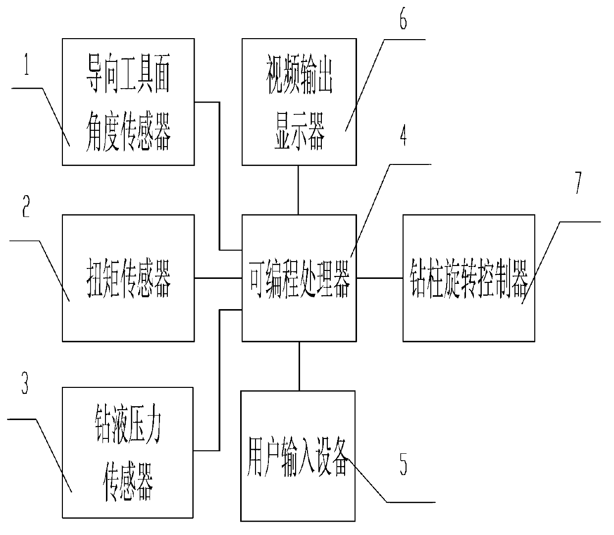
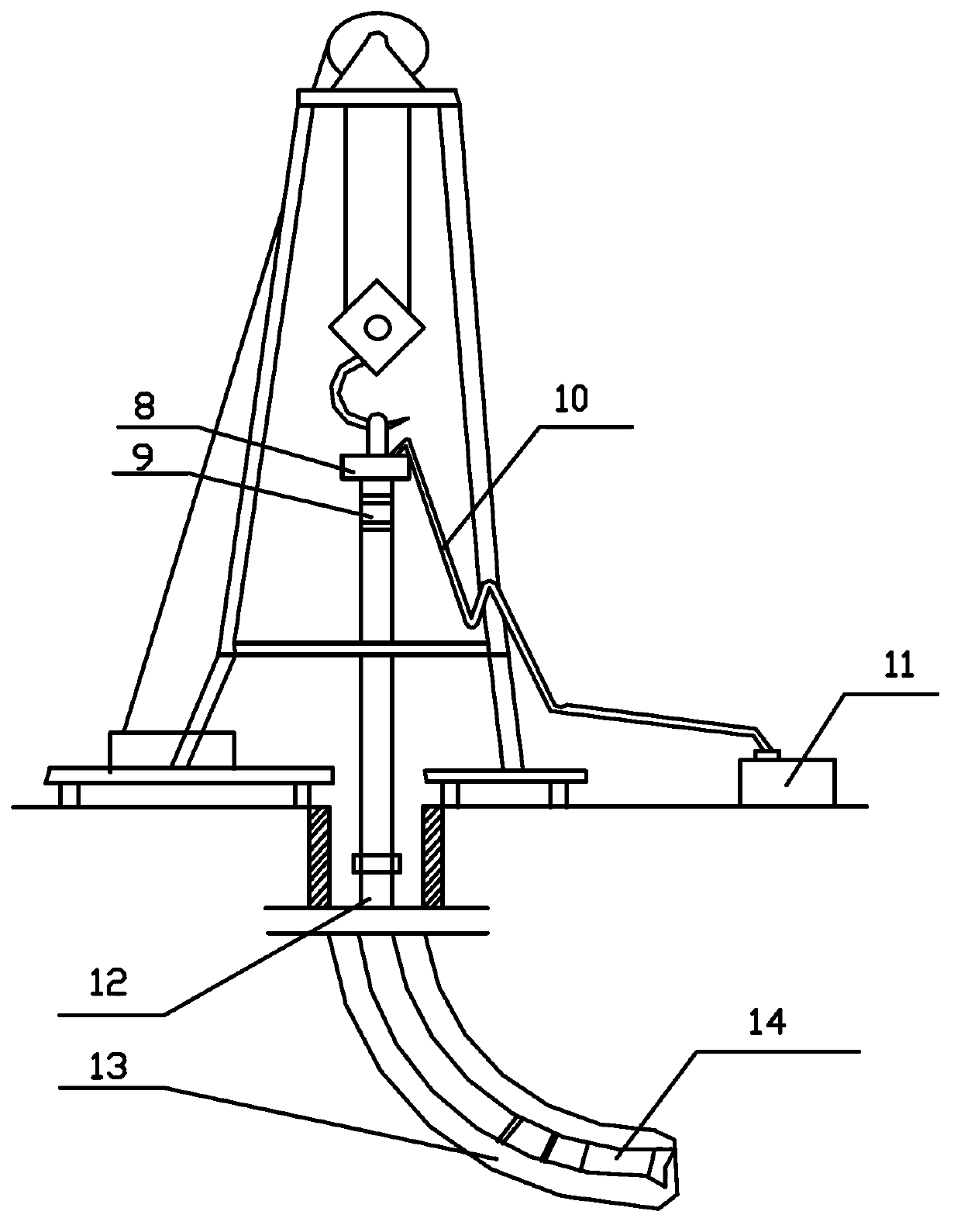
[0012] The automatic sliding drilling control device of the present invention is composed of a steering tool face angle sensor 1, a torque sensor 2, a drilling fluid pressure sensor 3, a programmable processor 4, a user input device 5, a video output display 6, and a drill string rotation controller 7; The above-mentioned steering tool face angle sensor 1 is installed in the bottom hole assembly 13. The steering tool face angle sensor 1 uses mud pulse telemetry to send a signal to the receiver on the ground, and the ground receiver outputs a steering tool face angle signal for transmission. to the programmable processor 4 for processing; the steering tool face angle signal is generated at a rate of once every 20 seconds, which is an indication signal used to measure the tool face angle of the steerable drilling motor 14; the torque sensor 2 is installed I...


PUM


Abstract

The invention relates to an automatic sliding well drilling control device, and belongs to the technical field of oil drilling tool design. The automatic sliding well drilling control device is characterized by being composed of a guiding tool face angle sensor (1), a toque sensor (2), a drilling fluid pressure sensor (3), a programmable processor (4), a user input device (5), a video output displayer (6) and a drill column rotating controller (7). The programmable processor (4) is used for receiving output signals form the guiding tool face angle sensor (1), the toque sensor (2) and the drilling fluid pressure sensor (3), the output signals is processed by the programmable processor (4) and the received information and a processing result are displayed on the video output displayer (6). After the programmable processor (4) processes the received information, the programmable processor (4) outputs a control instruction to the drill column rotating controller (7) and controls the drill column rotating controller (7). According to the automatic sliding well drilling control device, a tool face can be modified and oriented fast and accurately, the conversion between the sliding and the rotating drilling is fast, the drilling ability in a horizontal section is enhanced, and the automatic sliding well drilling control device has the advantages that mechanical drilling speed is increased, well track quality is improved, and the service life of a motor under a well is prolonged.

Description

Technical field: [0001] The invention relates to an automatic sliding drilling control device, which belongs to the technical field of oil drilling tool design. Background technique: [0002] Rotary steerable drilling technology and motor / measurement-while-drilling technology are commonly used tools in directional drilling. Due to the high cost of rotary steerable tools and the requirements for wellbore size, they are not economically feasible; The measurement-while-drilling system includes a downhole motor and a motor bending casing. During the sliding drilling process, the drill string does not rotate, but slides along the axial direction of the well wall, and the wellbore trajectory is positioned by bending the casing section. Therefore, During the drilling process, there are problems such as low wellbore purification efficiency, large friction when the pipe string is advanced, and the steerable motor is easy to stall. As a result, the ROP of the steerable motor sliding d...

Claims


Application Information

Patent Timeline
Patent Type & Authority Applications(China)
IPC IPC(8): E21B7/04E21B44/02
Inventor 易先中吉源强
Owner YANGTZE UNIVERSITY
Why Eureka
Try Eureka