Patch antenna

A patch antenna and microstrip patch technology, which is applied in the direction of resonant antenna, with multiple scattered linear units, and radiation element structure, can solve the problems of difficult antenna design for dual-frequency satellite navigation receivers, etc. Achieve the effects of easy processing and debugging, easy processing, and improved working bandwidth

Inactive Publication Date: 2013-09-04
GUANGDONG UNIV OF TECH
View PDF4 Cites 16 Cited by
  • Summary
  • Abstract
  • Description
  • Claims
  • Application Information

AI Technical Summary

Problems solved by technology

Although the current GNSS dual-frequency receiving microstrip antenna technology has matured, how to greatly increase the frequency bandwidth and axial ratio bandwidth of the patch antenna while reducing the size is still a difficult point in the design of the dual-frequency satellite navigation receiver antenna.

Method used


Image

  • Patch antenna
  • Patch antenna
  • Patch antenna

Examples


Embodiment

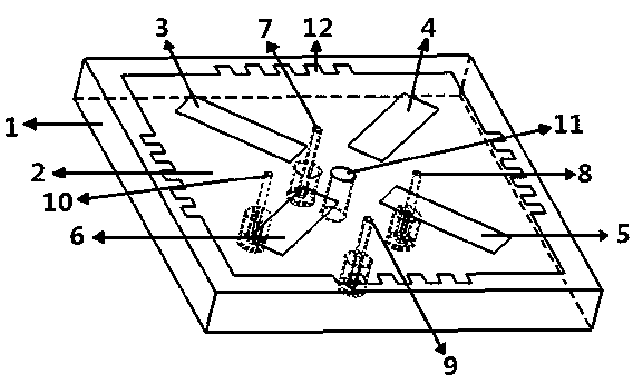
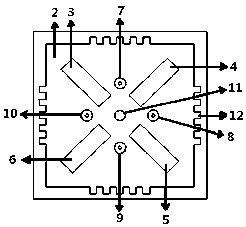
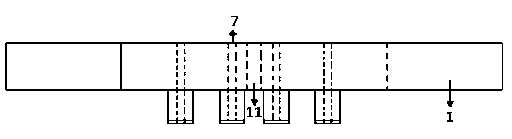
[0023] The structure diagram of the present invention is as figure 1 , 2 , 3, the patch antenna of the present invention includes a dielectric substrate 1 and a microstrip patch 2, and the surface of the microstrip patch 2 is respectively provided with four radiation grooves 3, 4, 5 along the diagonal position of the dielectric substrate 1 , 6, the four radiation slots 3, 4, 5, 6 are distributed in a cross shape, and the microstrip patch 2 is provided with four feed points 7, 8, 9, 10, wherein the horizontal geometric center line and the longitudinal geometric center There are two feed points on the line respectively, and the four feed points 7, 8, 9, 10 are symmetrical to the geometric center of the microstrip patch 2, and feed lines are provided at the feed points for feeding. The patch antenna of the present invention greatly widens the working bandwidth and axial ratio bandwidth of the antenna due to the adoption of the cross-shaped distribution of radiation slots and the...


PUM


Abstract

The invention relates to a patch antenna, which comprises a dielectric substrate (1) and a microstrip patch (2), wherein four radiating grooves (3, 4, 5 and 6) are respectively arranged on a surface of the microstrip patch (2) along diagonal positions of the dielectric substrate (1), and are distributed in a cross shape; four feeding points (7, 8, 9 and 10) are arranged on the microstrip patch (2); two feeding points are respectively arranged on a horizontal geometric center line and a longitudinal geometric center line; and the four feeding points (7, 8, 9 and 10) are symmetrical to a geometric center of the microstrip patch (2), and are provided with feeder lines for feeding. The patch antenna has wider impedance bandwidth and axial ratio bandwidth, and higher gain; the miniaturization of a structural dimension can be realized; and the stability performance of a phase center is better. According to the patch antenna, not only are the impedance bandwidth and the axial ratio bandwidth of the patch antenna greatly improved, but also favorable circular polarization performance and miniaturization effect are achieved, and the patch antenna is particularly suitable for an accurate measurement type navigation terminal.

Description

technical field [0001] The invention relates to a patch antenna, in particular to a microstrip antenna in the field of satellite navigation, in particular to a dual-frequency antenna applied to a high-precision measurement satellite navigation receiving terminal, and belongs to the innovative technology of a patch antenna. Background technique [0002] With the continuous development of satellite navigation and measurement technology, satellite navigation and positioning system has also been widely developed and applied. At present, many countries around the world have established their own satellite navigation and positioning systems, such as China's Beidou system, the United States' GPS system, Russia's GLONASS system, and Europe's GALILEO system. With the continuous maturity of these satellite systems and the continuous deepening of the civilian application process, as one of the key technologies of GNSS, the high-performance receiving equipment-the satellite navigation s...

Claims


Application Information

Patent Timeline
Patent Type & Authority Applications(China)
IPC IPC(8): H01Q1/36H01Q9/44
Inventor 林福民李庚禄
Owner GUANGDONG UNIV OF TECH
Why Eureka
Try Eureka