Pressurized-water corrosion inhibiting structure for water release building

A technology for drainage structures and connecting pipes, which is used in construction, water conservancy projects, marine engineering and other directions, can solve the problems of blocking the development and collapse of cavitation bubbles, and cannot reduce erosion damage.

Active Publication Date: 2013-09-11
POWERCHINA ZHONGNAN ENG
View PDF5 Cites 2 Cited by
  • Summary
  • Abstract
  • Description
  • Claims
  • Application Information

AI Technical Summary

Problems solved by technology

Water flow aeration can effectively retard the development and collapse of cavitation bubbles, water flow aeration can reduce cavitation damage, but cannot reduce erosion damage

Method used


Image

  • Pressurized-water corrosion inhibiting structure for water release building
  • Pressurized-water corrosion inhibiting structure for water release building

Examples


Embodiment 1

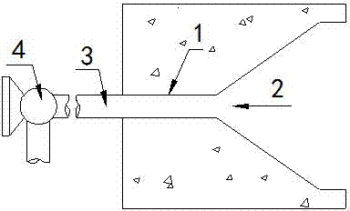
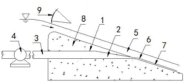
[0014] see Figure 1 to Figure 2 , the pressurized water corrosion reduction structure of the drainage structure includes a communication pipe 1 buried in the interior of the drainage structure 8; the inlet end 3 of the communication pipe 1 is externally connected to the pressure water device 4; the outlet end 2 of the communication pipe 1 is connected to the The flow wall 7 of the drainage structure 8 is connected, the outlet end 2 of the connecting pipe 1 is a trumpet-shaped flat orifice, and the connecting pipe 1 is a steel pipe; the water pressure equipment 4 is a water pump. The discharge structure 8 is provided with a discharge gate 9 , and the pressurized water equipment 4 is linked with the opening and closing system of the discharge gate 9 .

[0015] The drainage width of the drainage structure 8 is 5m, the connecting pipe 1 is a steel pipe, and its diameter is consistent with the diameter of the inlet and outlet of the external water pump 4, which is 650mm; the water...


PUM


Abstract

The invention provides a pressurized-water corrosion inhibiting structure for a water release building. The pressurized-water corrosion inhibiting structure comprises a communication pipe embedded into the water release building. Pressurized-water equipment is connected with the outside of the inlet end of the communication pipe. The outlet end of the communication pipe is communicated with the flow-passing wall face of the water release building and is a flat porthole. The pressurized-water corrosion inhibiting structure can press and pour a low-flow-speed water body to the bottom of a high-flow-speed area of the flow-passing wall face so that a low-flow-speed area can be formed between the flow-passing wall face and the high-speed water flow, and the high-speed water flow can not directly act on the flow-passing wall face. Meanwhile, the high-speed water flow and the low-speed water flow generate the shearing, blending and entraining effect, a large amount of water flow kinetic energy is consumed, the bottom flow speed of the high-speed water flow can be lowered, water flow cavitation is inhibited, and damage of cavitation corrosion and flush corrosion is avoided.

Description

technical field [0001] The invention relates to a pressurized water corrosion reduction structure of a drainage structure, in particular to a water body with a low flow rate injected into the bottom of a high-speed water flow of a drainage structure, thereby reducing the bottom flow velocity of the high-speed water flow, suppressing cavitation of the water flow, and reducing cavitation damage and erosion-damaged structures. Background technique [0002] Under the action of high-speed water flow, the concrete surface of the drainage structure is prone to cavitation damage and erosion damage, and even brings fatal damage to the drainage structure. Cavitation and erosion damage are sometimes serious on the drainage structure. occur. [0003] At present, aeration facilities are often installed on high-speed water discharge structures, and the air is entrained into the water body by the dragging effect of the water flow on the aeration facilities. Water flow aeration can effect...

Claims


Application Information

Patent Timeline
Patent Type & Authority Applications(China)
IPC IPC(8): E02B8/06
Inventor 戴晓兵
Owner POWERCHINA ZHONGNAN ENG
Why Eureka
Try Eureka