Double seal linkage pilot spool structure of high pressure differential valve

A pilot spool and double-seal technology, which is applied in the direction of the valve's fluid energy absorption device, valve lift, valve details, etc., can solve the problems of reduced sealing ability of the valve, insufficient sealing ability of the hard sealing surface, and creep under pressure, etc. Achieve the effects of reducing erosion and cavitation damage, improving reliability and prolonging service life

Active Publication Date: 2016-09-14
沈阳古来科技有限公司
View PDF7 Cites 0 Cited by
  • Summary
  • Abstract
  • Description
  • Claims
  • Application Information

AI Technical Summary

Problems solved by technology

Due to the influence of many factors, this method has proved that its sealing reliability is not ideal in practical applications: First, because the sealing surface is a single metal sealing surface, when the valve is in the closed state, impurities are stuck on the metal sealing surface When the sealing surface is not closed tightly, the sealing surface will be damaged by the erosion of the leakage medium, which will reduce the sealing ability of the valve; second, the balanced valve core only relies on an elastic energy storage sealing ring to achieve sealing, due to the elastic energy storage of plastic material The performance and reliability of the sealing ring will be affected by the working temperature of the valve, which will also lead to poor sealing reliability of the valve
[0005] The high-pressure differential regulating valve products of Masoneilan (Masoneilan) in the United States, when the valve has high sealing requirements, adopt a hard-soft sealing combination structure that rolls a soft sealing ring on the inner side of the metal hard sealing surface on the valve seat. , the sealing ability of the valve is stronger than that of a single metal seal, but this structure also has some shortcomings in use: First, due to the pressure creep of the soft sealing material, the soft sealing surface and hard sealing surface of the valve are difficult to maintain in the long-term It can always maintain an ideal matching state and sufficient sealing specific pressure at the same time; second, when the valve core is close to the closed state, the soft sealing surface with poor anti-scourability will withstand relatively more high-speed flowing media. Affect its sealing performance
There are three disadvantages of this structure: First, the large sealing force required when the metal sealing surface of the inner valve core is closed is only composed of the spring force of several small springs plus the limited up and down pressure of the medium acting on the inner valve core The structure is poor, and the sealing ability of the hard sealing surface is relatively insufficient; the second is that several bolts fixing the inner valve core and the spring are welded to the upper part for reliable anti-loosening, and it is inconvenient to disassemble the valve core during maintenance; the third is that although the valve core is Balanced spool, when closed, the force of the medium will not damage the seal of the hard and soft sealing surfaces, but it cannot improve the sealing ability of the valve by means of the medium pressure like the pressurized spool with flow-off design. enhanced

Method used


Image

  • Double seal linkage pilot spool structure of high pressure differential valve
  • Double seal linkage pilot spool structure of high pressure differential valve
  • Double seal linkage pilot spool structure of high pressure differential valve

Examples


Embodiment Construction

[0034] The technical solutions of the present invention will be further described below in conjunction with the drawings and embodiments.

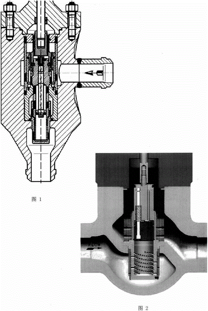
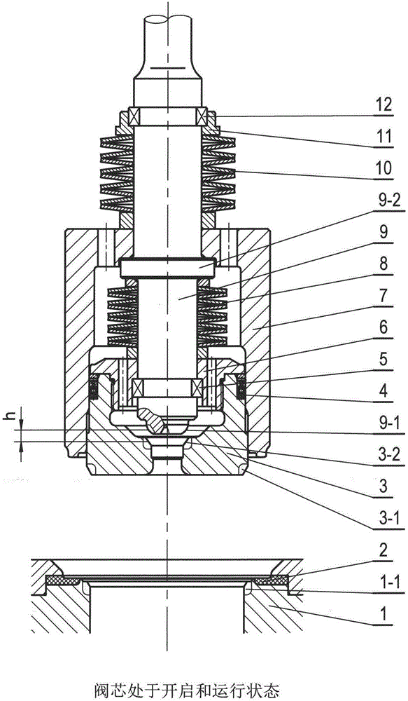
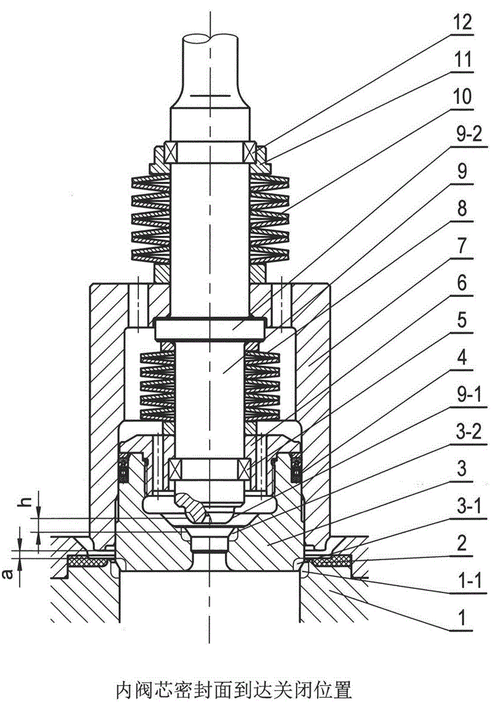
[0035] Such as Figure 3 ~ Figure 6 As shown, it is a schematic diagram of the technical solution for applying the double-seal linkage pilot spool structure proposed by the present invention to the structural design of the high pressure difference minimum flow regulating valve in thermal power plants. The valve is designed for the medium flow direction of the flow-close type with top in and bottom out.

[0036] The integral spool assembly structure of the valve is provided with two spools: the outer spool (7) and the inner spool (3). The outer spool (7) is cylindrical with a platform on the upper end, and its lower end surface is closed. The sealing surface coincides with the soft sealing ring (2) installed and fixed on the outside of the hard sealing surface (1-1) of the valve seat (1), and the outer circle lower end of the inner valve c...


PUM


Abstract

The invention discloses a double-seal linkage pilot valve element structure of a high-pressure-difference valve. According to the technical scheme, a fixing ring is installed and fixed on an outer circle of the lower end of a valve rod, and an inner valve element assembly is installed and connected to the lower end of the valve rod through the fixing ring. An annular boss is arranged on the outer circle of the valve rod, and a lower spring is pre-tightened and installed between the annular boss and the inner valve element assembly of the valve rod in a sleeved mode. The outer circle of an inner valve element is enclosed by an inner hole of the lower segment of an outer valve element in a sleeved mode, the outer valve element and the inner valve element move relative to each other in the axial direction while the valve is closed up, and a sealing ring is located between the outer valve element and the inner valve element. A platform at the upper end of the outer valve element is located on the upper side of the annular boss of the valve rod, a spring thrust ring is fixed to the valve rod, and an upper spring is pre-tightened and installed between the spring thrust ring and the upper plane of the outer valve element in a sleeved mode. A plurality of balance holes are formed in a valve element cover and the upper end of the outer valve element. According to the technical scheme, the double-seal linkage pilot valve element structure of the high-pressure-difference valve has the advantages that the valve can achieve high sealing capacity, scour and cavitation erosion damage to the sealing face is reduced, meanwhile, the using reliability of the valve is improved, and the service life of the valve is prolonged.

Description

technical field [0001] The invention relates to a valve structure, in particular to a double-seal valve core structure of a high-pressure differential valve. Background technique [0002] High pressure differential valves are often important valves and key valves in units and systems in power plants, petrochemical industries, etc. Their performance and reliability have a crucial impact on the safe and stable operation of units and systems. For example, the feedwater recirculation regulating valve, desuperheating water regulating valve, air-to-air exhaust valve, turbine bypass valve, etc. installed and used in the water vapor circulation system of thermal power plants are all used under high pressure differential conditions. Due to the high pressure difference on both sides of the sealing surface of the high-pressure differential valve, if the sealing capacity of the sealing surface is insufficient and leakage occurs, the medium in the leakage channel will reach a high flow r...

Claims


Application Information

Patent Timeline
Patent Type & Authority Patents(China)
IPC IPC(8): F16K1/36F16K1/46F16K1/48F16K47/02
CPCF16K1/00F16K1/36F16K1/46F16K1/482F16K47/023
Inventor 章华
Owner 沈阳古来科技有限公司
Why Eureka
Try Eureka