A dam spillway structure and its construction method

A technology for spillways and dams, applied in the field of spillways, can solve the problems of cavitation damage, low energy dissipation rate, and insufficient flow aeration on the stepped surface, and achieve the effect of reducing cavitation damage and improving efficiency and efficiency.

Active Publication Date: 2021-11-19
广东粤源工程咨询有限公司
View PDF7 Cites 0 Cited by
  • Summary
  • Abstract
  • Description
  • Claims
  • Application Information

AI Technical Summary

Problems solved by technology

However, engineering practice has shown that with the increase of flow single width and discharge, due to the increase of water depth at the bottom surface of the spillway, the initial cross-section of aeration moves downward, resulting in insufficient flow aeration, and the step surface of the spillway is prone to cavitation damage, resulting in low energy dissipation rate
[0004] For the related technologies mentioned above, the inventor believes that there is a defect of low energy dissipation rate

Method used


Image

  • A dam spillway structure and its construction method
  • A dam spillway structure and its construction method
  • A dam spillway structure and its construction method

Examples


Embodiment 1

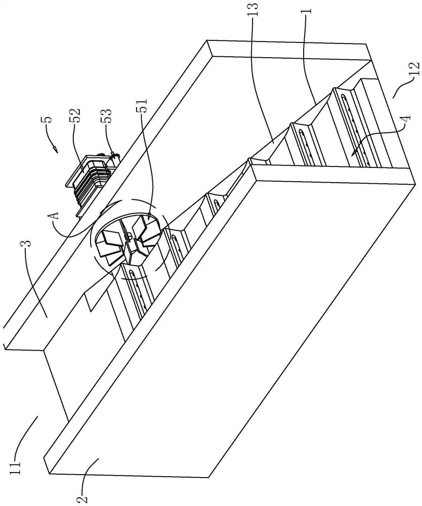
[0046] refer to figure 1 , a dam spillway structure, including a channel body bottom plate 1 extending obliquely, a first side plate 2 and a second side plate 3 formed on the inclined surface of the channel body bottom plate 1, and multiple side plates arranged on the channel body bottom plate 1 inclined surface A stepped body 4, an inflation mechanism 5 installed on the top of the second side plate 3.

[0047] refer to figure 1 , the bottom plate of the channel body 1 is arranged on an incline, the higher end of the channel body bottom plate 1 is the inlet 11, and the lower end of the horizontal position is the outlet 12, and the water flow flows out from the inlet 11 along the channel bottom plate 1 to the outlet 12; The first side plate 2 and the second side plate 3 are all formed on the top of the channel body bottom plate 1, the first side plate 2 and the second side plate 3 are all vertical extensions, and the first side plate 2 and the second side plate 3 are spaced ap...

Embodiment 2

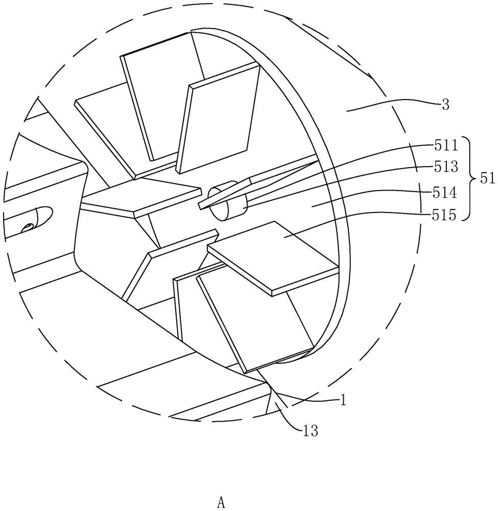
[0071] refer to Figure 4 , Figure 5 , The difference between Embodiment 2 and Embodiment 1 is that the inflation mechanism 5 includes a rotating member 51 and an inflation body 6 . The specific structure of the rotating member 51 is the same as that of the rotating member 51 in the first embodiment.

[0072] refer to Figure 5 , The inflatable body 6 includes a mounting plate 61 , blades 62 , a casing 63 , and a circular tube 64 . The mounting plate 61 is fixedly sleeved on the rotating rod 513; the blade 62 is fixedly connected to the outer wall of the mounting plate 61 away from the second side plate 3, and the blade 62 is rotationally symmetrical along the axis of the rotating rod 513; the housing 63 is sleeved on the mounting plate 61. The outside of the plate 61 and the blade 62, the housing 63 is a hollow cylinder inside the housing 63, the axis of the housing 63 coincides with the axis of the rotating rod 513, and the outer wall of the housing 63 is fixedly connect...


PUM


Abstract

The application relates to a dam spillway structure and its construction method, which includes a channel bottom plate arranged obliquely, a first side plate and a second side plate formed on the upper surface of the channel bottom plate; one end of the channel bottom plate is the entrance, The other end is the exit, and the bottom plate of the channel body is inclined downward from the entrance to the exit; the upper part of the bottom plate of the channel body is provided with a plurality of steps along the drainage direction; the step body includes a straight surface and a vertical surface; There is a ventilation groove, the ventilation groove extends along the extension direction of the step body and one end runs through the second side plate, and gas is passed into the ventilation groove. The application has the effect of improving the energy dissipation rate of the spillway.

Description

technical field [0001] The application relates to the field of spillways, in particular to a dam spillway structure and a construction method thereof. Background technique [0002] At present, the spillway is the flood control equipment and discharge structure of the water conservancy structures such as the reservoir, and it is mostly built on one side of the dam. The spillway generally does not work frequently, but it is an important building in the reservoir hub. The spillway is like a large trough, which is used to vent the flood that cannot be accommodated by the planned reservoir. When the water level in the reservoir exceeds the safe limit, the water will flow downstream from the spillway to prevent the dam from being destroyed. Therefore, the importance of the spillway to the dam is self-evident. However, the dam spillway is directly exposed to the atmosphere and is affected by the natural environment, and its foundation is prone to typical seepage erosion damage. T...

Claims


Application Information

Patent Timeline
Patent Type & Authority Patents(China)
IPC IPC(8): E02B8/06
CPCE02B8/06
Inventor 戴跃华李威余列强梁娟李燕邓美姣
Owner 广东粤源工程咨询有限公司
Why Eureka
Try Eureka