Method and device for overhauling tailwater cooler

A technology for overhauling devices and coolers, which is used in hydropower, hydraulic engineering, hydropower stations, etc., can solve the problem of poor accuracy of underwater alignment installation and removal of tail water coolers, difficult underwater operations, and high risks. problems, to improve maintenance efficiency, reduce cavitation damage, and achieve good hydraulic conditions.

Pending Publication Date: 2018-11-16
CHINA POWER CONSRTUCTION GRP GUIYANG SURVEY & DESIGN INST CO LTD
View PDF0 Cites 0 Cited by
  • Summary
  • Abstract
  • Description
  • Claims
  • Application Information

AI Technical Summary

Problems solved by technology

[0002] For hydropower projects with large sediment content and many impurities, the tail water cooler usually adopts the circulating cooling water supply method. The tail water cooler is installed on the upper platform of the parapet wall on the side of the tail water outlet maintenance gate unit. Considering that the cooling effect will not be affected, the tail water The cooler is set at the lower part of the normal tail water level as a whole. In the existing technology, divers are used to install and remove the tail water cooler; the specific method is as follows: during maintenance, divers are used to dive to the installation support of the cooler, and the tail water is lifted out after removing the connecting bolts. Cooler inspection, after the inspection is completed, put the tailwater cooler, and then send divers to dive to the installation support of the cooler to connect and fix it. It is very troublesome to ask divers every time during inspection, and it is even more inconvenient for remote places. The underwater alignment installation and removal accuracy of the tail water cooler is poor, and the underwater operation is difficult and dangerous. Therefore, there are still deficiencies in the existing technology and need to be further improved

Method used


Image

  • Method and device for overhauling tailwater cooler
  • Method and device for overhauling tailwater cooler
  • Method and device for overhauling tailwater cooler

Examples


Embodiment

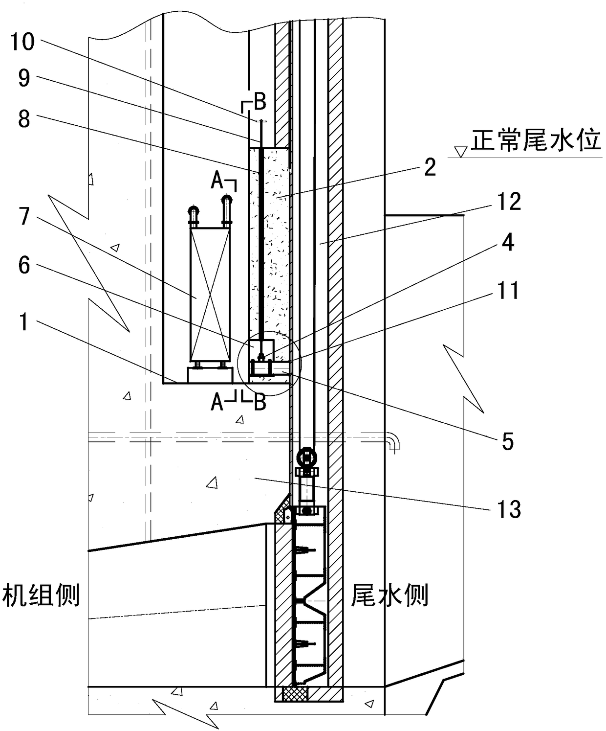
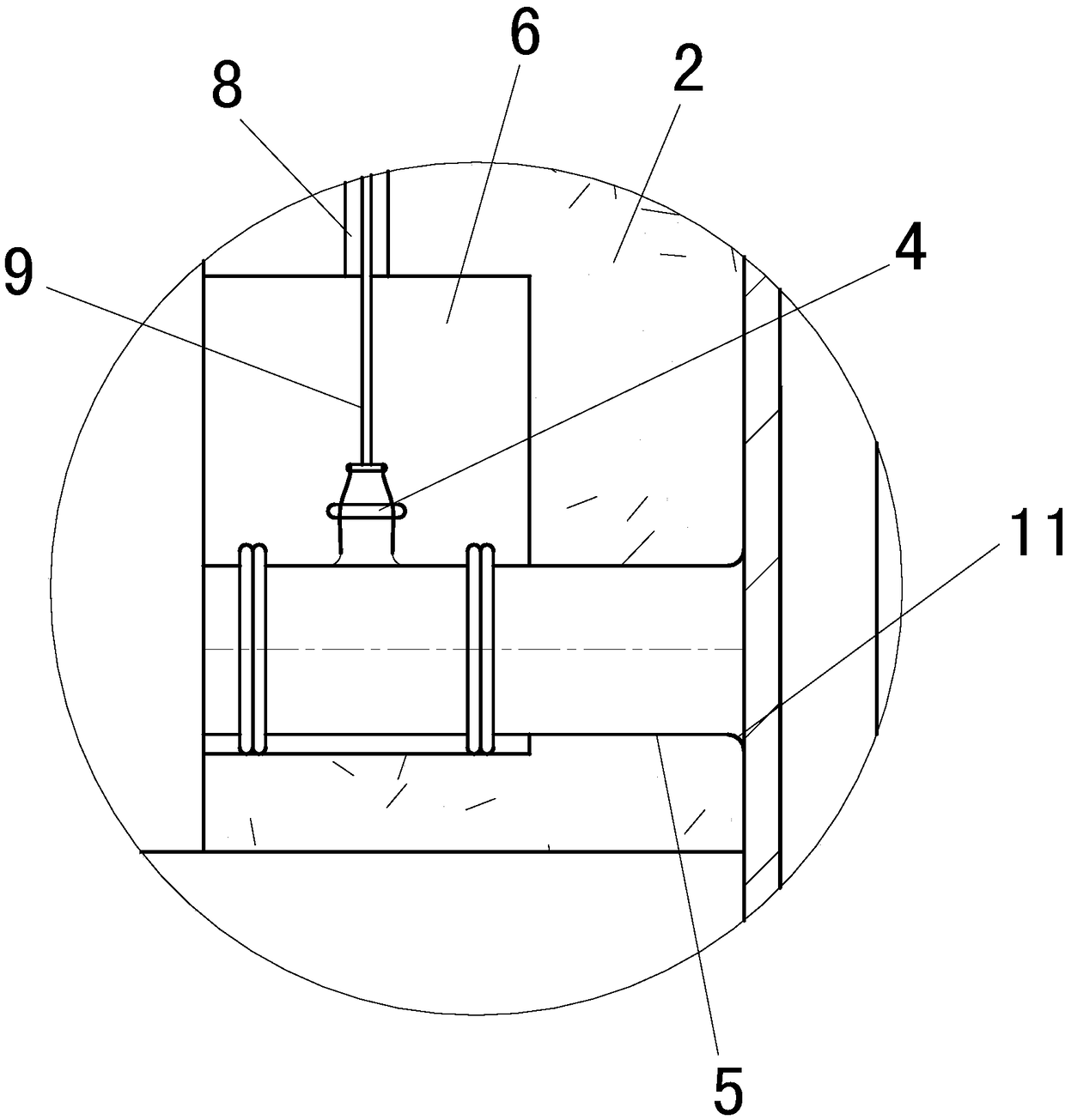
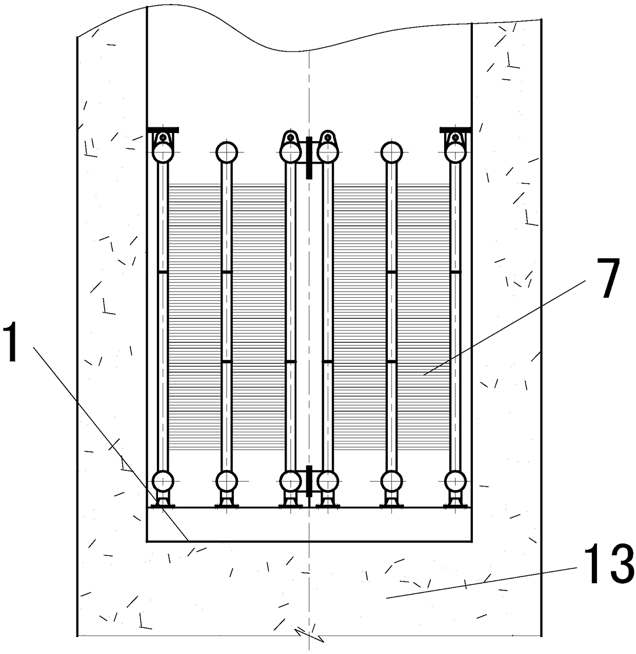
[0028] The maintenance method of the tail water cooler in this example is as follows: Figure 1~4 As shown, a water retaining wall 2 is set on the upper platform 1 of the parapet wall on the side of the unit, and a valve 4 arranged in an isosceles triangle 3 is arranged on the side of the water retaining wall 2 from top to bottom. The valve 4 communicates with the tail water side through a steel pipe 5. The steel pipe 5 is fixed on the retaining wall 2, and the valve 4 is located in the operating room 6. The tail water cooler 7 is set on the upper platform 1 on the top surface of the breast wall 13 on the unit side; the top of the water retaining wall 2 is slightly higher than the normal tail water level, and the water retaining wall 2 is provided with a vertical hole 8; the vertical hole 8 is used to place the connecting valve 4 of the operating rod 9; the handle 10 of the operating rod 9 is located above the top of the retaining wall 2; as figure 2 As shown, the outlet on ...


PUM


Abstract

The invention discloses a method and device for overhauling a tailwater cooler. The tailwater cooler is located at the top surface of an upper platform. According to the method, a water retaining wallis built on the edge of the top surface of the upper platform, wherein the top of the water retaining wall is slightly higher than the normal tailwater level or the elevation of the generating waterlevel of a unit; steel pipes communicating with a gate slot hole are arranged in the water retaining wall, valves are installed on the steel pipes, and when the tailwater cooler needs to be overhauled, all valves are closed first, and the water body on the side, close to the tailwater cooler, of the water retaining wall is discharged through a temporary water pump; afterwards, the tailwater cooleris overhauled; after overhaul work is completed and overhaul personnel leave the upper platform, water filling and pressure balancing are performed on the tailwater cooler side of the water retainingwall through the temporary water pump, and all the valves are opened so that water areas on two sides of the water retaining wall communicate with each other to realize cooling of the tailwater cooler. In the process of overhauling according to the method, the tailwater cooler does not need to be lifted away from the upper platform, underwater operation is not needed, and therefore overhauling and maintenance can be carried out very conveniently, overhauling efficiency can be improved, and the personal safety of the overhauling personnel can be ensured.

Description

technical field [0001] The invention relates to a method and device for overhauling a tail water cooler, belonging to the technical field of metal structures of water conservancy and hydropower projects. Background technique [0002] For hydropower projects with large sediment content and many impurities, the tail water cooler usually adopts the circulating cooling water supply method. The tail water cooler is installed on the upper platform of the parapet wall on the side of the tail water outlet maintenance gate unit. Considering that the cooling effect will not be affected, the tail water The cooler is set at the lower part of the normal tail water level as a whole. In the existing technology, divers are used to install and remove the tail water cooler; the specific method is as follows: during maintenance, divers are used to dive to the installation support of the cooler, and the tail water is lifted out after removing the connecting bolts. Cooler inspection, after the i...

Claims


Application Information

Patent Timeline
Patent Type & Authority Applications(China)
IPC IPC(8): E02B9/06E02B7/54
CPCE02B7/54E02B9/06Y02E10/20
Inventor 王兴恩李月彬谭守林莫春霞
Owner CHINA POWER CONSRTUCTION GRP GUIYANG SURVEY & DESIGN INST CO LTD
Why Eureka
Try Eureka