Ski-jump and jet flow combined energy dissipation device

A technology of energy dissipation device and test device, which is applied in water conservancy projects, sea area projects, coastline protection, etc., and can solve problems such as restrictions on the use of scour pits

Active Publication Date: 2013-09-25
嘉善永升五金厂
View PDF4 Cites 5 Cited by
  • Summary
  • Abstract
  • Description
  • Claims
  • Application Information

AI Technical Summary

Problems solved by technology

Some dams now use scour pits to form water cushions, but this method has many defects: for example, when the anti-scour capacity of the bedrock is not

Method used


Image

  • Ski-jump and jet flow combined energy dissipation device
  • Ski-jump and jet flow combined energy dissipation device

Examples


Embodiment Construction

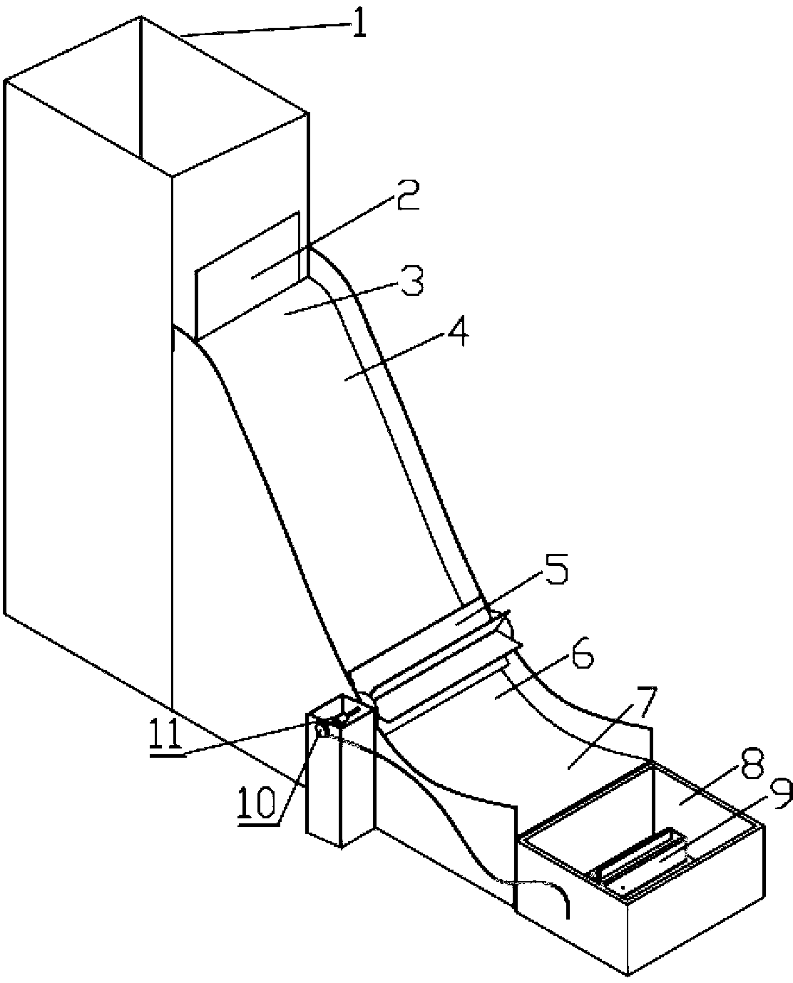
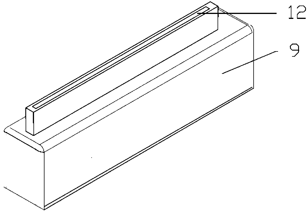
[0012] Such as Figure 1~2 As shown, the device is composed of a reservoir, a dam body, a dam surface, an impeller, a generator, a high-pressure water pump, a cushion pond, a bearing, a coupling, and a transmission.

[0013] The water outlet 2 of the reservoir is consistent with the top 4 of the dam. When the water in the reservoir 1 reaches a certain amount, the water in the reservoir 1 will be stably discharged from the top 4 along the dam surface 3 in the form of surface flow. Form a surface flow. The nose sill part of the dam surface is composed of a circular arc section 6 with a central angle of 53° and a circular arc section 7 with a scoop angle of 25°, which realizes the turning of the water flow and the protruding surface does not produce excessive impact on the dam. The impeller 5 is composed of 5 blades with a length×width of 600 mm×105 mm, and the left and right sides of the impeller are circles with a radius of 65 mm. The lowest point of the impeller blades is 5mm a...


PUM


Abstract

The invention discloses a ski-jump and jet flow combined energy dissipation device. The ski-jump and jet flow combined energy dissipation device is composed of an impounding reservoir, a dam crest, a dam surface, an impeller, a transmission, a generator, a high pressure water pump and a plunge pool. The generator and the impeller are coaxial. The high pressure water pump is arranged inside the plunge pool. High-velocity water flow discharged from a dam top is utilized for impacting the impeller on the overflow dam surface, the impeller rotates to drive the generator to generate electricity and supply power for the high pressure water pump in the plunge pool. The surface-shaped jet flow sprayed upwards from the water pump and the surface-shaped water flow discharged after being flipped by the overflow dam surface collide in the air and dissipate energy. The ski-jump and jet flow combined energy dissipation device has the advantage of dissipating energy by a sill, nappe convection and the plunge pool, has high energy dissipation efficiency.

Description

Technical field: [0001] The invention relates to a jet and jet combined energy dissipation device, which belongs to the technical field of dam flood discharge and energy dissipation technology, and can simultaneously realize the three main purposes of bottom sill energy dissipation, power generation and energy storage, and offset energy dissipation. Background technique: [0002] In recent years, with the implementation of the country's western development and the strategy of power transmission from west to east, a number of high dams of 200 to 300 m level will be built in the western mountain and valley areas. These projects generally have the characteristics of high-head and large-flow flood discharge, which increases the difficulty of the layout of the discharge structure, and there is a contradiction between excessive flood discharge power and small downstream energy dissipation space. In the high-head water conservancy and hydropower project, the problem of high-speed water ...

Claims


Application Information

Patent Timeline
IPC IPC(8): E02B8/06
Inventor 戎贵文李琦丁杰吴福贤陈丽周军乔润利
Owner 嘉善永升五金厂
Why Eureka
Try Eureka