Liquid delivery device and liquid delivery method
A technology of conveying device and conveying direction, which can be used in liquid variable volume machinery, pumps with flexible working elements, machines/engines, etc., and can solve problems such as difficulties
- Summary
- Abstract
- Description
- Claims
- Application Information
AI Technical Summary
Problems solved by technology
Method used
Image

Examples
no. 1 Embodiment approach
[0043]
[0044] As an aspect of the liquid transport device used in this embodiment, a liquid transport pump 1 that transports a liquid by peristaltic motion of a tube will be described as an example. Representative examples of the liquid transported by the liquid transport pump 1 include water, saline solution, medicinal liquid, oil, fragrance liquid, ink, etc., but other fluid liquids may also be transported.
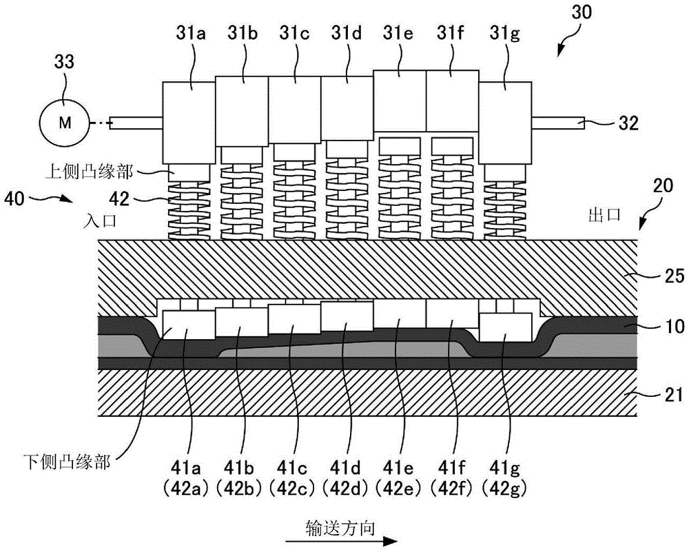
[0045] figure 1 It is a schematic cross-sectional view of the liquid-sending pump 1 of the first embodiment. The liquid delivery pump 1 has a tube 10 , a tube holding unit 20 , a drive unit 30 and a compression unit 40 .
[0046] The tube 10 is made of an elastic circular tubular material, and the liquid to be transported is filled in the circular tube. In addition, the tube 10 performs a peristaltic motion by being sequentially compressed by finger portions 41a to 41g described later, thereby transferring the liquid filled inside. In the liquid delivery pump 1, ...
no. 2 Embodiment approach
[0093] In the first embodiment, when the release operation is performed, the elastic body ( figure 1 The elastic bodies 42a to 42g) generate elastic force, thereby moving the fingers in the releasing direction, but the fingers may also be moved by other methods.
[0094] Figure 7 It is a schematic diagram showing the structure of the liquid-sending pump 2 of the second embodiment. In the liquid-feeding pump 2 , elastic members corresponding to the elastic bodies 42 a to 42 g of the liquid-feeding pump 1 are not provided. Other structures are roughly the same as the liquid delivery pump 1 .
[0095] In the present embodiment, the fingers 41 a to 41 g are moved in the releasing direction by the restoring force of the tube 10 during the release operation. That is, the finger portion is pushed up in the releasing direction by utilizing the force that the shape of the tube 10 that has been crushed during the compressing operation tends to return to its original shape. In this ...
no. 3 Embodiment approach
[0099] In the liquid delivery pump 3 of the third embodiment, the tube 10 is arranged in a circumferential shape, and the liquid filled in the tube is transported by compressing and releasing the tubes 10 radially around the central rotation axis. .
[0100]
[0101] Figure 8 It is a schematic diagram showing the structure of the liquid-sending pump 3 of the third embodiment. The liquid delivery pump 3 has a tube 10 , a tube holding unit 20 , a drive unit 30 and a compression unit 40 .
[0102] The tube 10 is the same as that described in each of the above-mentioned embodiments, but in the liquid feeding pump 3, the tube 10 is held as Figure 8 Such a circular shape (arc shape). In the present embodiment, the liquid is transported in the circumferential direction along the tube 10 maintained in a circumferential shape. That is, the conveying direction of the liquid is the circumferential direction.
[0103] The tube holder 20 has a guide wall 22 and a restriction wall ...
PUM
 Abstract
Description
Claims
Application Information
 - R&D
- Intellectual Property
- Life Sciences
- Materials
- Tech Scout
- Unparalleled Data Quality
- Higher Quality Content
- 60% Fewer Hallucinations
Browse by: Latest US Patents, China's latest patents, Technical Efficacy Thesaurus, Application Domain, Technology Topic, Popular Technical Reports.
© 2025 PatSnap. All rights reserved.Legal|Privacy policy|Modern Slavery Act Transparency Statement|Sitemap|About US| Contact US: help@patsnap.com