

Data transmission method and device
A data transmission method and a technology for sending data, which are applied in the field of data transmission methods and devices, can solve the problems of low frequency diversity gain and small data transmission coverage, and achieve the effect of improving frequency diversity gain
- Summary
- Abstract
- Description
- Claims
- Application Information
AI Technical Summary
Problems solved by technology
Method used
Image

Examples
Embodiment 1
[0081] The preferred embodiment provides an enhanced frequency hopping manner for uplink resources, which can obtain more frequency diversity gain without increasing control overhead.
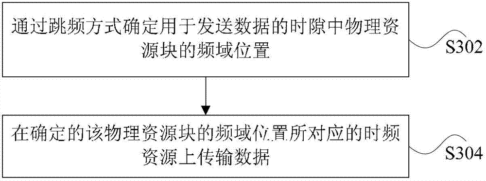
[0082] In this preferred embodiment, the transmitter determines the frequency domain position of the physical resource block in the time slot used for sending data through frequency hopping, and initializes the random sequence c in the frequency hopping through the following parameters: cell identification and frame sequence number. Better,
[0083] Preferably, the inter-subband Hopping function f hop (i) Determined by:
[0084]
[0085] Preferably, the Hopping function f in the subband m (i) Determined by:
[0086]
[0087] In this preferred embodiment, when uplink frequency hopping is enabled, time slot n s The physical resource block used for uplink transmission is determined according to the following formula:
[0088]
[0089] Preferably, i is determined by one of the following methods:
[0090] ...
Embodiment 2
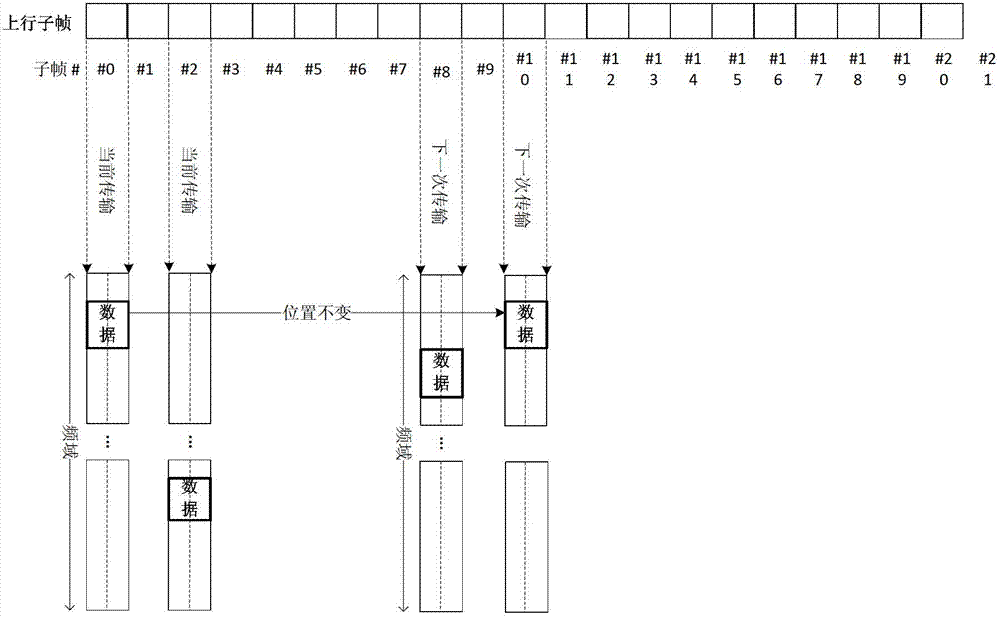
[0096] The preferred embodiment provides a data transmission method, Figure 5 It is a schematic diagram of enhanced type 2 inter-subframe resource hopping according to an embodiment of the present invention, such as Figure 5 As shown, subframe 0 and subframe 8 are resource positions occupied by the first transmission and retransmission of data, and subframe 2 and subframe 10 are resource positions occupied by the first transmission and retransmission of data.
[0097] In this preferred embodiment, data transmission can be performed according to the following formula:
[0098] Physical resource block offset index:
[0099] (Formula 1)
[0100] Among them, the frequency hopping variable (Formula 2)
[0101] Among them, the subband frequency hopping function (Formula 3)
[0102] Among them, the image frequency hopping function f m (i)=c(10*i) Formula 4
[0103] Among them, the number of resource blocks in the subband (Formula 5)
[0104] among them, (Formula 6)
[0105] (Formula 7)
[0...
Embodiment 3
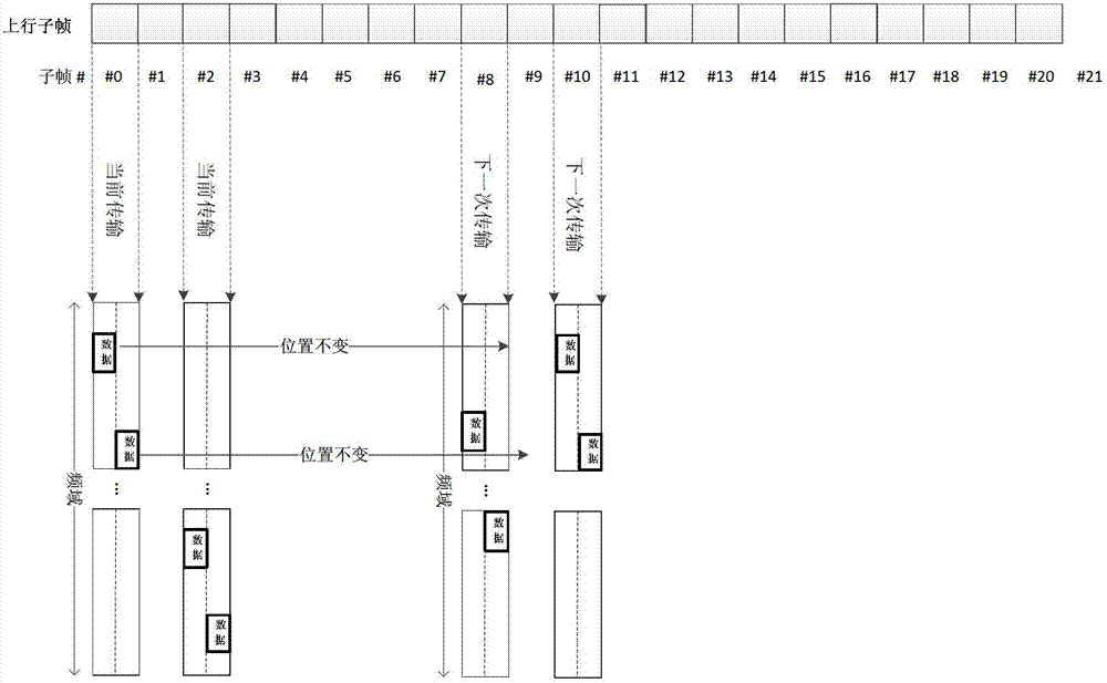
[0121] The preferred embodiment provides a data transmission method, Image 6 It is a schematic diagram of enhanced type 2 inter-subframe and intra-subframe resource hopping according to an embodiment of the present invention, such as Image 6 As shown, subframe 0 and subframe 8 are resource positions occupied by the first transmission and retransmission of data, and subframe 2 and subframe 10 are resource positions occupied by the first transmission and retransmission of data.
[0122] In this preferred embodiment, data transmission can be performed according to the following formula:
[0123] Physical resource block offset index:
[0124] (Formula 8)
[0125] Among them, the frequency hopping variable i=n s (Formula 9)
[0126] Among them, the subband frequency hopping function (Formula 10)
[0127] Among them, the image frequency hopping function f m (i)=c(10*i) formula (11)
[0128] Among them, the number of resource blocks in the subband (Formula 12)
[0129] among them, (Formula...
PUM
 Abstract
Description
Claims
Application Information