Method and apparatus in node for wireless communication

A technology for wireless communication and node equipment, applied in wireless communication, baseband systems, digital transmission systems, etc., to achieve the effect of improving frequency diversity gain, ensuring receiving performance, and reducing complexity

Pending Publication Date: 2022-01-14
SHANGHAI LANGBO COMM TECH CO LTD
View PDF0 Cites 0 Cited by
  • Summary
  • Abstract
  • Description
  • Claims
  • Application Information

AI Technical Summary

Problems solved by technology

Although some new features have been introduced in Version 15 (Release 15) and Version 16 (Release 16) to support different IoT application scenarios, such as Ultra-reliable and Low Latency Communications (URLLC, Ultra-reliable and Low Latency Communications) and Industrial Internet of Things (IIoT, Industrial Internet of Things), but for some other application scenarios, such as wearable devices, surveillance video, etc., standard support is still required

Method used


Image

  • Method and apparatus in node for wireless communication
  • Method and apparatus in node for wireless communication
  • Method and apparatus in node for wireless communication

Examples


Embodiment 1

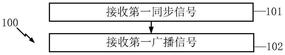
[0072] Embodiment 1 illustrates the flowchart of the first synchronization signal and the first broadcast signal according to an embodiment of the present application, as shown in the attached figure 1 shown. in the attached figure 1 In the figure, each block represents a step, and it should be emphasized that the order of the blocks in the figure does not represent the chronological relationship between the steps represented.

[0073] In Embodiment 1, the first node device in this application receives the first synchronization signal in step 101; receives the first broadcast signal in step 102, the first broadcast signal carries a target index, and the target index is a non-negative Integer; wherein, the first synchronization signal occupies the first time-frequency resource set, the second time-frequency resource set is occupied by the first broadcast signal, and the target time-frequency resource subset is orthogonal to the second time-frequency resource set , the target ...

Embodiment 2

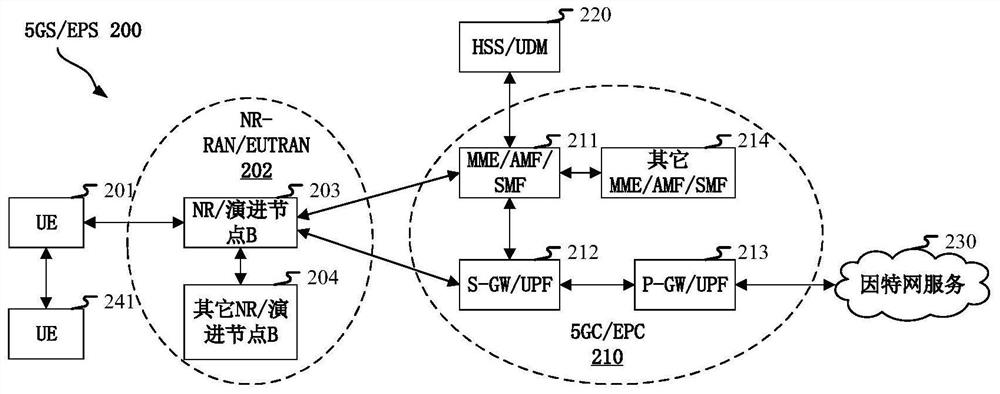
[0237] Embodiment 2 illustrates a schematic diagram of a network architecture according to the present application, as attached figure 2 shown. attached figure 2A diagram illustrating a network architecture 200 of 5G NR, LTE (Long-Term Evolution, long-term evolution) and LTE-A (Long-Term Evolution Advanced, enhanced long-term evolution) systems. The 5G NR or LTE network architecture 200 may be referred to as 5GS (5G System) / EPS (Evolved Packet System, Evolved Packet System) 200 or some other suitable terminology. 5GS / EPS 200 may include one or more UE (User Equipment, user equipment) 201, NG-RAN (next generation radio access network) 202, 5GC (5G Core Network, 5G core network) / EPC (Evolved Packet Core, evolution Packet Core) 210, HSS (Home Subscriber Server, Home Subscriber Server) / UDM (Unified Data Management, Unified Data Management) 220 and Internet Service 230. 5GS / EPS can be interconnected with other access networks, but these are not shown for simplicity entity / inte...

Embodiment 3

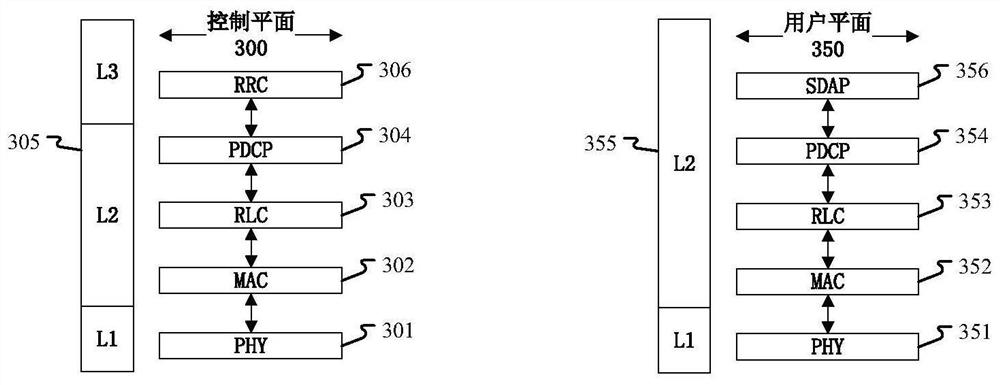
[0245] Embodiment 3 shows a schematic diagram of an embodiment of a wireless protocol architecture of a user plane and a control plane according to the present application, as shown in the attached image 3 shown. image 3 is a schematic diagram illustrating an embodiment of a radio protocol architecture for a user plane 350 and a control plane 300, image 3 The radio protocol architecture of the control plane 300 for the first node device (UE or gNB) and the second node device (gNB or UE) is shown in three layers: Layer 1 , Layer 2 and Layer 3 . Layer 1 (L1 layer) is the lowest layer and implements various PHY (Physical Layer) signal processing functions. The L1 layer will be referred to herein as PHY 301 . Layer 2 (L2 layer) 305 is above the PHY 301 and is responsible for the link between the first node device and the second node device through the PHY 301 . The L2 layer 305 includes a MAC (Medium Access Control, Media Access Control) sublayer 302, an RLC (Radio Link Cont...


PUM


Abstract

The invention discloses a method and an apparatus in a node for wireless communication. A node receives a first synchronization signal and a first broadcast signal, wherein the first broadcast signal carries a target index; a first synchronization signal occupies a first time-frequency resource set, a second time-frequency resource set is occupied by the first broadcast signal, and the target time-frequency resource subset and the first time-frequency resource set comprise the same symbol in a time domain; the type of the first node device is used for determining whether the target time-frequency resource subset is occupied by the first broadcast signal; the subcarrier interval of subcarriers included by the first time-frequency resource set in a frequency domain is equal to a first subcarrier interval, and the first time-frequency resource set is used for determining the first subcarrier interval in a frequency band to which the frequency domain belongs; the target index determines whether the first broadcast signal carries a first information block, and the first information block determines a control resource set. According to the invention, broadcast channel performance is improved.

Description

technical field [0001] The present application relates to a transmission method and device in a wireless communication system, and in particular to a transmission scheme and device for a device with reduced capability in wireless communication. Background technique [0002] The application scenarios of future wireless communication systems are becoming more and more diversified, and different application scenarios put forward different performance requirements for the system. In order to meet the different performance requirements of various application scenarios, the new air interface technology (NR, New Radio) (or 5G) research, passed the WI (Work Item, work item) of the new air interface technology (NR, New Radio) at the 3GPP RAN#75 plenary meeting, and started to standardize NR. [0003] In the new air interface technology, IoT applications are an important part. Although some new features have been introduced in Version 15 (Release 15) and Version 16 (Release 16) to s...

Claims


Application Information

Patent Timeline
Patent Type & Authority Applications(China)
IPC IPC(8): H04W72/12H04W72/04H04L27/26H04L25/02
CPCH04W72/1263H04L25/0224H04W72/0446H04W72/0453H04L27/2601
Inventor 刘铮张晓博
Owner SHANGHAI LANGBO COMM TECH CO LTD
Why Eureka
Try Eureka