Brake system having an electromagnetic track brake device

A technology of magnetic rail braking and braking equipment, which is applied in the direction of brakes, brakes, and operating mechanisms of railway vehicle brakes that interact with braking elements and rails, and can solve problems such as wear and tear and insignificant magnetic rail braking devices

Active Publication Date: 2014-04-23
KNORR BREMSE SYST FUR SCHIENENFAHRZEUGE GMBH
View PDF6 Cites 9 Cited by
  • Summary
  • Abstract
  • Description
  • Claims
  • Application Information

AI Technical Summary

Problems solved by technology

Here, the magnetic track brake is subject to insignificant wear

Method used


Image

  • Brake system having an electromagnetic track brake device
  • Brake system having an electromagnetic track brake device

Examples


Embodiment Construction

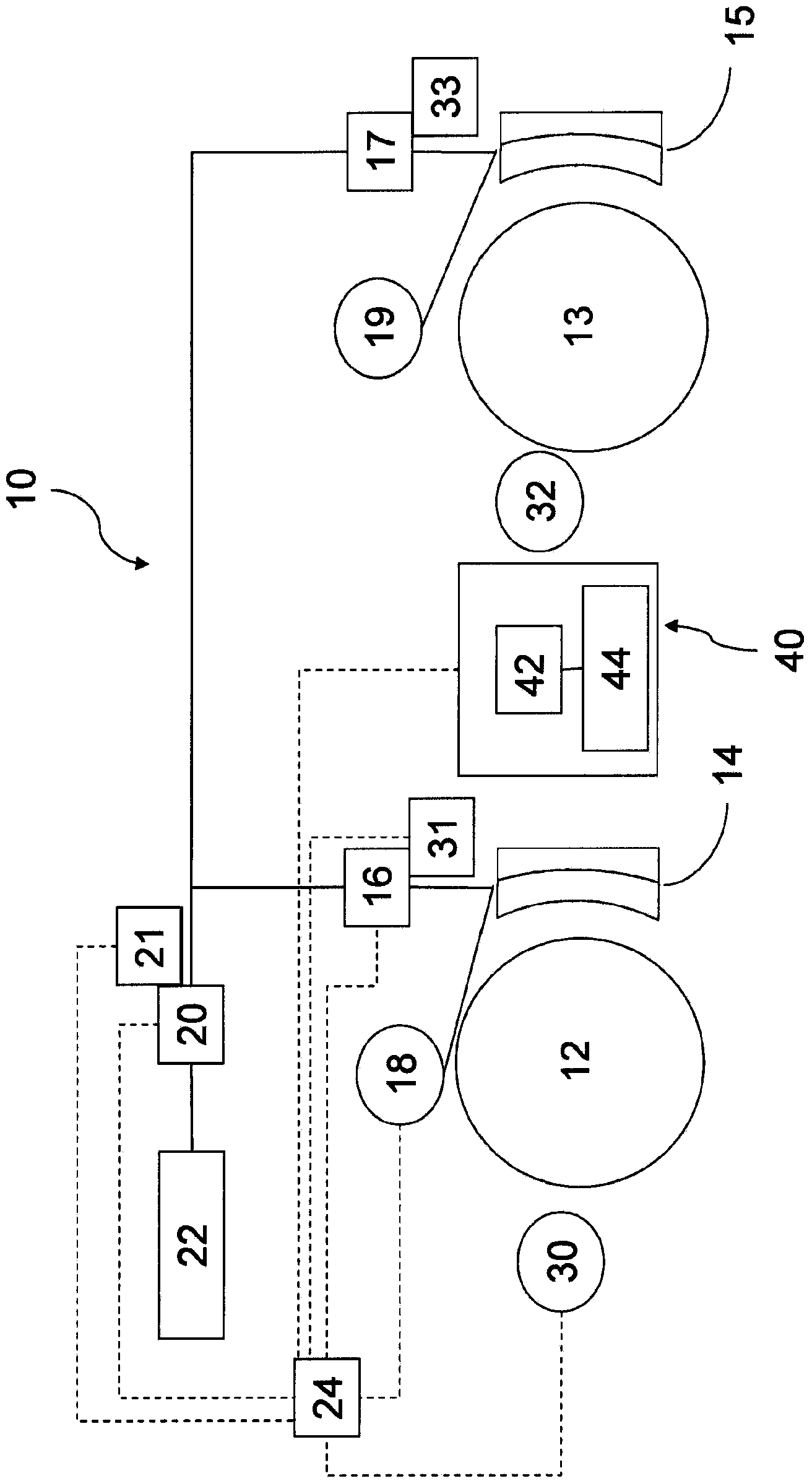
[0021] figure 1 A schematic diagram of a braking system 10 of a rail vehicle with a pneumatic service brake is shown. Mechanical and pneumatic connections and lines are shown in solid lines, while electrical connections or communication channels are shown in dashed lines. The braking system 10 is provided for braking wheels 12 and 13 of a rail vehicle. In this example, the wheels 12 and 13 are located on different axles, but on one bogie. A first brake shoe 14 is associated with the first wheel 12 . A second brake shoe 15 is associated with the second wheel 13 . Each brake shoe 14 , 15 has a brake shoe braking surface, which brakes the associated wheel when the brake shoe is pressed against the sliding surface of the associated wheel 12 , 13 by means of the brake shoe surface. The brake shoe 14 can be actuated for braking by means of a force generator 16 . The force generator 16 is connected via a power supply line to the main control valve arrangement 20 . Compressed ai...


PUM


Abstract

The invention relates to a brake control device (24) for a brake system (10), wherein the brake system (10) has at least one electromagnetic track brake device (40), which can be supplied with current at variable amperage according to the brake control device (24) in order to create a braking force, and wherein the brake control device (24) is designed to actuate the at least one electromagnetic track brake device (40) at a cleaning amperage during travel in order to clean a rail. The invention further relates to a brake system having such a brake control device, a rail vehicle, and a method for cleaning a rail by means of an electromagnetic track brake device.

Description

technical field [0001] The invention relates to a brake control device for a rail vehicle, a brake device with a magnetic rail brake device, a brake device with such a brake control device, a rail vehicle and a A method for controlling at least one magnetic rail brake device of a braking system of a rail vehicle. Background technique [0002] Modern rail vehicles usually have a brake system with a plurality of differently acting brake devices. Usually a service brake is provided, such as a pressure-operated brake, for example a hydraulic or pneumatic brake. Furthermore, eddy current brakes, vehicle retarders or also magnetic track brakes are additionally used. In contrast to eddy current brakes, magnetic rail brakes here are friction brakes which are in frictional contact with the rail during actuation. The magnetic track brake is magnetized by energization and strongly attached to the track. In this case, the magnetic track brake is subject to insignificant wear. In pa...

Claims


Application Information

Patent Timeline
Patent Type & Authority Applications(China)
IPC IPC(8): B61H7/08E01H8/00
CPCE01H8/10B60T1/04B61H7/00B61H13/00B08B7/00B61H7/08B61H11/00
Inventor 马尔科格雷戈里·埃尔斯托尔普夫
Owner KNORR BREMSE SYST FUR SCHIENENFAHRZEUGE GMBH
Why Eureka
Try Eureka