LED (light-emitting diode) backlight driving circuit, backlight module and liquid crystal display device

A technology of backlight drive circuit and LED light bar, which is applied to static indicators, instruments, etc., can solve problems such as rising costs, achieve high conversion efficiency, reduce energy consumption, and reduce production costs

Inactive Publication Date: 2014-06-18
TCL CHINA STAR OPTOELECTRONICS TECH CO LTD
View PDF4 Cites 10 Cited by
  • Summary
  • Abstract
  • Description
  • Claims
  • Application Information

AI Technical Summary

Problems solved by technology

[0003] The range that cannot be boosted by using a booster line is limited, generally within 100V. If the voltage needs to be further increased, an additional step-up device such as a transformer needs to be added, resulting in an increase in cost

Method used


Image

  • LED (light-emitting diode) backlight driving circuit, backlight module and liquid crystal display device
  • LED (light-emitting diode) backlight driving circuit, backlight module and liquid crystal display device
  • LED (light-emitting diode) backlight driving circuit, backlight module and liquid crystal display device

Examples


Embodiment Construction

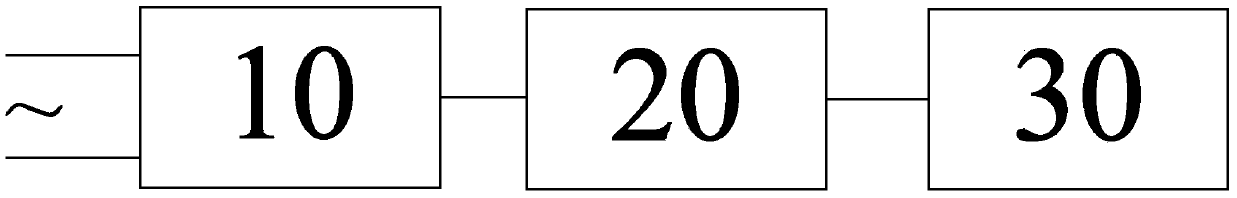
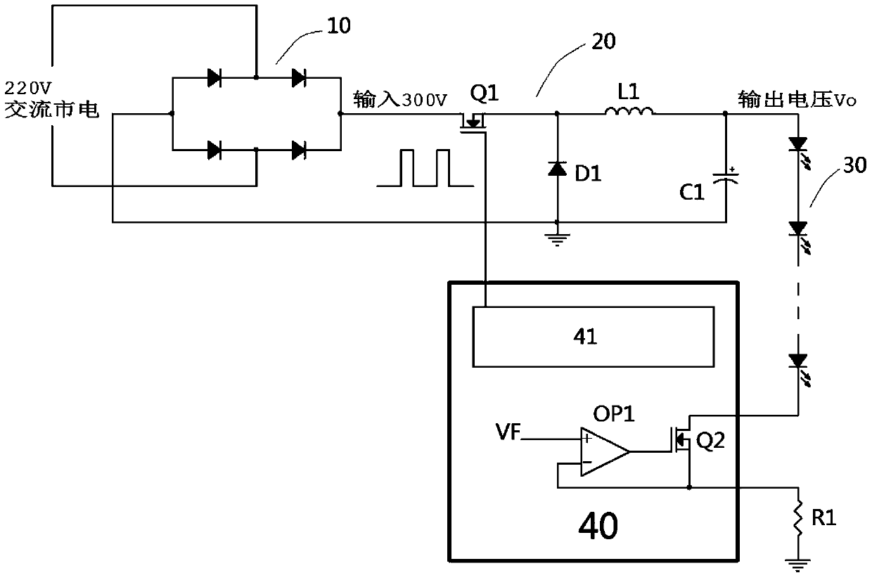
[0025] The invention discloses a liquid crystal display device. The liquid crystal display device includes a liquid crystal panel and a backlight module providing light source for the liquid crystal panel. The backlight module includes an LED backlight driving circuit. Such as figure 2 As shown, the LED backlight drive circuit includes a rectifier module 10 directly connected to the mains, a step-down module 20 coupled to the rectifier module 10 and controlled by PWM, and an LED light bar 30 directly coupled to the step-down module 20 .

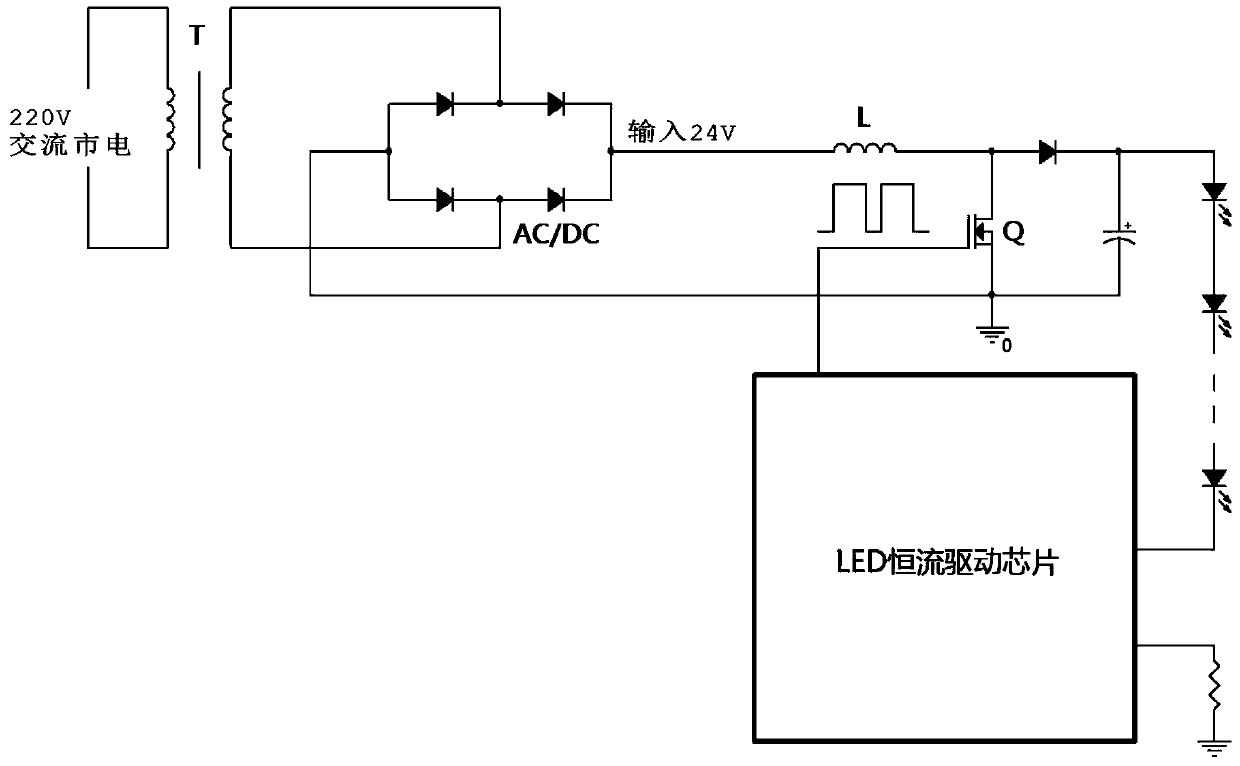
[0026] After research, according to the calculation formula of the boost circuit: Vo=Vin / (1-D), when the voltage Vo required by the LED light bar is high, the duty cycle D of the MOS tube driving signal will also increase, which means that in The conduction time of the voltage-regulating controllable switch in one cycle increases, and the current flowing in the MOS tube is relatively large, which will cause power loss and heat generation, re...


PUM


Abstract

The invention discloses an LED (light-emitting diode) backlight driving circuit, a backlight module and a liquid crystal display device. The LED backlight driving circuit comprises a rectifier module which is directly connected with the mains supply, a voltage reduction module which is coupled with the rectifier module and is controlled by adopting PWM (pulse width modulation), and LED lamp strips which are coupled with the voltage reduction module. A transformer for the mains supply and the rectifier module is omitted, and boosting devices are unnecessary to be added under the occasion needing high voltage driving, so that the production cost of the whole circuit is undoubtedly reduced.

Description

technical field [0001] The invention relates to the field of liquid crystal display, and more specifically relates to an LED backlight driving circuit, a backlight module and a liquid crystal display device. Background technique [0002] The liquid crystal display device includes a liquid crystal panel and a backlight module, and the backlight module includes an LED backlight drive circuit. The existing LED backlight drive circuits all use booster circuits, such as figure 1 shown. The input 24V DC voltage is obtained by rectifying the 220V AC mains through the transformer T and the bridge rectifier circuit (AC / DC). The LED constant current drive chip controls the voltage regulation MOS tube Q to be turned on and off, and the inductor L completes energy storage and release. In the process of energy, a higher DC voltage is provided to the LED light bar, and the output voltage of the boost circuit Vo=Vin / (1-D) (D is the duty cycle of the MOS tube driving signal). [0003] The...

Claims


Application Information

Patent Timeline
IPC IPC(8): G09G3/34G09G3/36
Inventor 张华
Owner TCL CHINA STAR OPTOELECTRONICS TECH CO LTD
Why Eureka
Try Eureka