
High-voltage distribution device with double breakers used for single bus segmentation and application thereof
A single-busbar segmented, high-voltage power distribution technology, applied in circuit devices, busbar/line layout, electrical components, etc., can solve problems such as user loss, poor flexibility, loss, etc., to ensure reliability and stability, and ensure reliability. performance, stability, and overload avoidance
- Summary
- Abstract
- Description
- Claims
- Application Information
AI Technical Summary
Problems solved by technology
Method used
Image

Examples
Embodiment 1
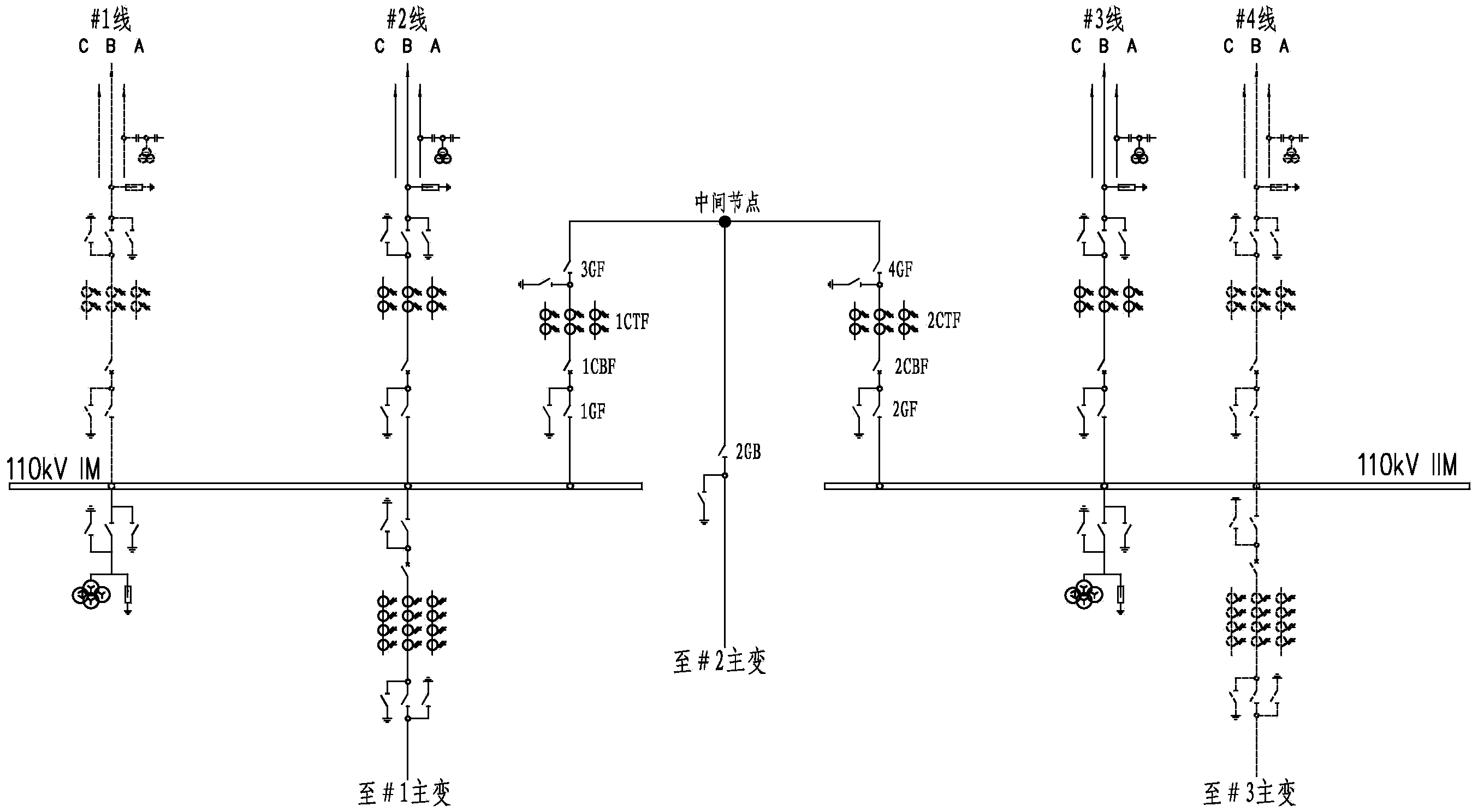
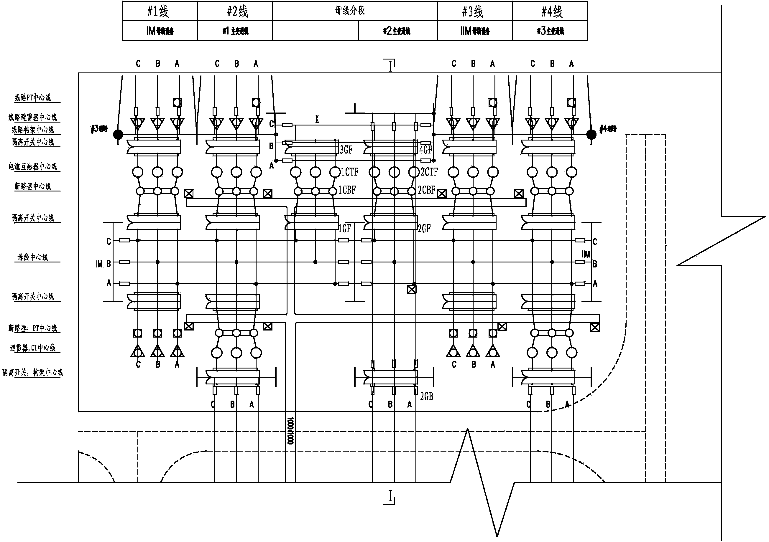
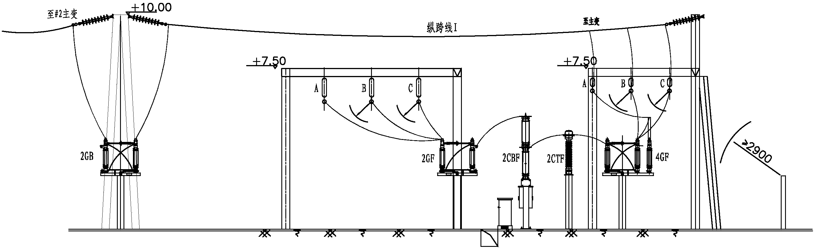
[0038] Refer to attached figure 1 , first provide the technical scheme of the high-voltage power distribution device with 4 circuit lines and 3 transformers: the high-voltage power distribution device with double circuit breakers as single busbar segmentation includes: the first segmental bus IM, the second segmental bus IIM and segmental circuits . Each segmental bus is connected with 2 return lines (incoming line and outgoing line) and 1 main transformer, and the main transformers connected to the first segmental bus IM and the second segmental bus IIM are respectively #1 main transformer and # 3 main transformers, and at least one of the two loops on each segment bus is a power line.
[0039] The section circuit includes a first circuit breaker 1CBF, a second circuit breaker 2CBF and an intermediate node; one end of the first circuit breaker 1CBF is connected to the first section bus IM through the first isolating switch 1GF, and the other end is connected through the fir...
Embodiment 2
[0047] Refer to attached Figure 4 , when the 110kV lines in the substation are 5 circuits, of which 3 circuits are power lines, the configuration method is roughly the same as that of embodiment 1, except that a power line is drawn out at the intermediate node. Specifically: the intermediate node is divided into intermediate node 1 and intermediate node 2, the intermediate node 1 is connected to #2 main transformer through the isolating switch 2GB; the intermediate node 2 is connected to a power line, through the fifth isolating switch 5G ), the third circuit breaker 3CB, the third current transformer 3CT and the seventh isolating switch 7G (outgoing line isolating switch) to form #5 line. Therefore, when the IM or IIM fails or is disconnected for maintenance, the third power supply line (i.e. #5 line) in the section circuit can supply power to the unfaulted section busbar and the main transformer on the section circuit , improving the stability and reliability of power supp...
Embodiment 3
[0052] According to Embodiment 1 of the present invention, the high-voltage power distribution device with double circuit breakers as single busbar section is applied to the renovation of old projects. That is to say, in the existing projects that have been put into operation, the high-voltage power distribution device of the single-bus section is transformed. Refer to attached Figure 9 , firstly, the equipment of the segmented circuit corresponds to the first isolating switch 1GF, the first circuit breaker 1CBF, the first current transformer 1CTF and The third isolating switch 3GF, and the isolating switch 2GB of the intermediate node, the second isolating switch 2GF, the second circuit breaker 2CBF, the second current transformer 2CTF, the fourth isolating switch 4GF and other equipment; then they are composed of integral SF6 gas The insulation combination equipment has a compact structure and can be placed in the interval where the single circuit breaker section was origi...
PUM
 Abstract
Description
Claims
Application Information