Information transfer equipment

a technology of information transfer equipment and equipment, applied in the field of information transfer equipment, can solve the problems of system processing performance extremely decline, equipment competitiveness impairment, and firmware operation stability, and achieve the effect of avoiding overloaded firmware sta

Inactive Publication Date: 2007-09-18
FUJITSU LTD
View PDF7 Cites 2 Cited by
  • Summary
  • Abstract
  • Description
  • Claims
  • Application Information

AI Technical Summary

Benefits of technology

[0057]It is accordingly an object of the present invention to provide an information transfer equipment comprising at least one channel portion; and a common portion for executing a monitoring control for each channel portion by transmitting / receiving monitoring control information to / from the channel portion, wherein the common portion executes a setting processing such as system setting information in the channel portion at a high speed without losing a fundamental characteristic of a CPU write access, and an overloaded state of a firmware is avoided.
[0073]In this case also, the usual operation of the firmware need not be suspended, so that it is made possible to avoid the firmware overloaded state.
[0076]Therefore, by storing the system setting information in the buffering portion, the data transmission requesting portion have only to request reading the buffering portion as necessary not through the CPU, so that processing of system setting information or the like can be executed at a high speed. Thus, the usual operation of the firmware need not be suspended, so that it is made possible to avoid the firmware overloaded state.
[0084]In this case also, the usual operation of the firmware need not be suspended, so that it is made possible to avoid the firmware overloaded state. Moreover, it is made possible to execute the channel switchover processing at a high speed.

Problems solved by technology

When signals such as the above-mentioned (1)-(4) are individually connected with leased cables, the competitiveness of the equipment is impaired in terms of size, cost, operational stability of the equipment, and the like.
Specifically, in an SDH wireless multiplexer where multi-channelization is noticeable, the simultaneous power ON / OFF of a plurality of channels is not a rare case, so that assuming the worst case of all of the channels, the system processing performance is to extremely decline.
Also, in the prior art information transfer equipment, there are following problems with respect to the operation of the firmware at the time of channel switchover.
However, by this interrupt processing, the performance of the monitoring control function executed by the firmware in a steady state declines.

Method used


Image

  • Information transfer equipment
  • Information transfer equipment
  • Information transfer equipment

Examples


embodiment (

3)

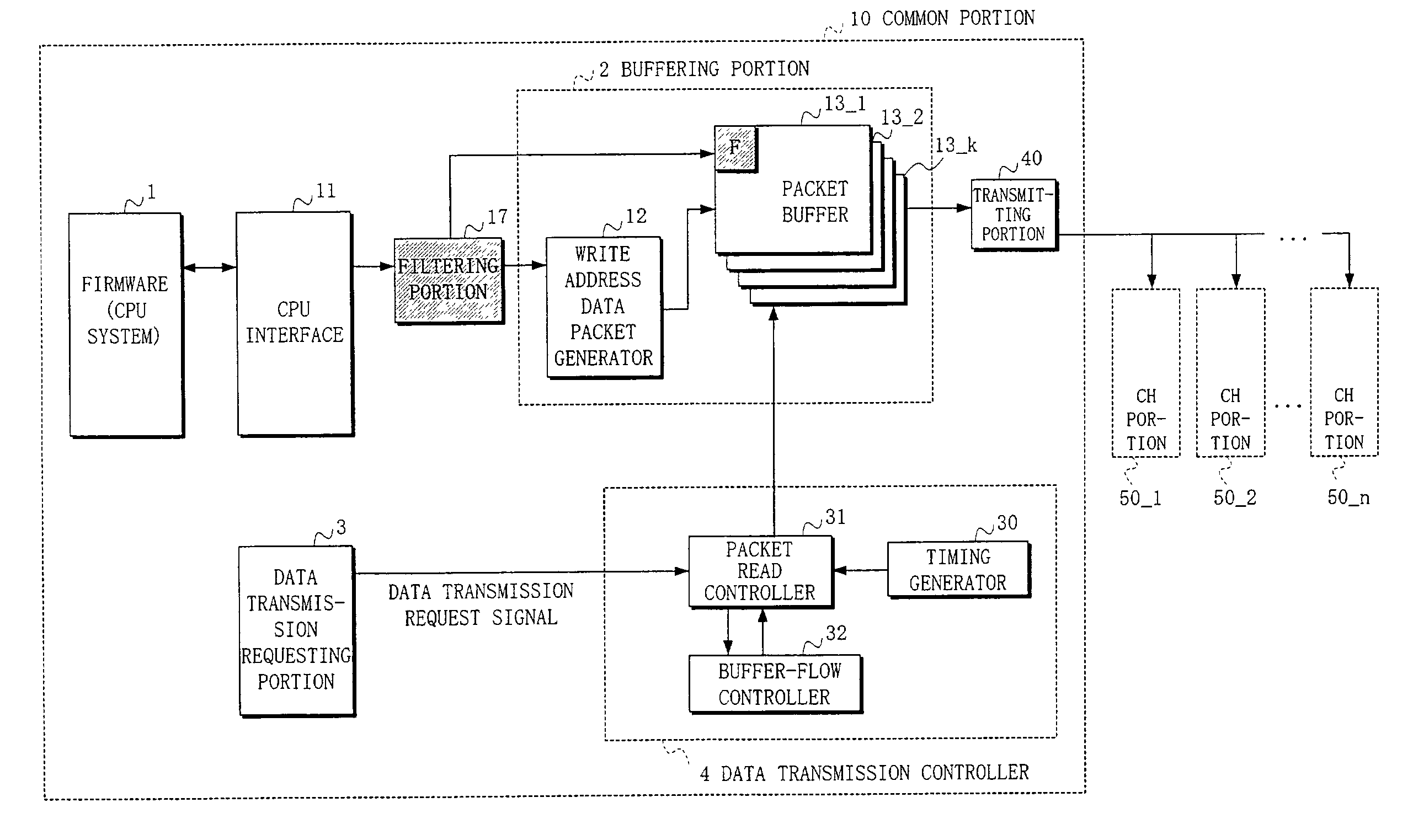
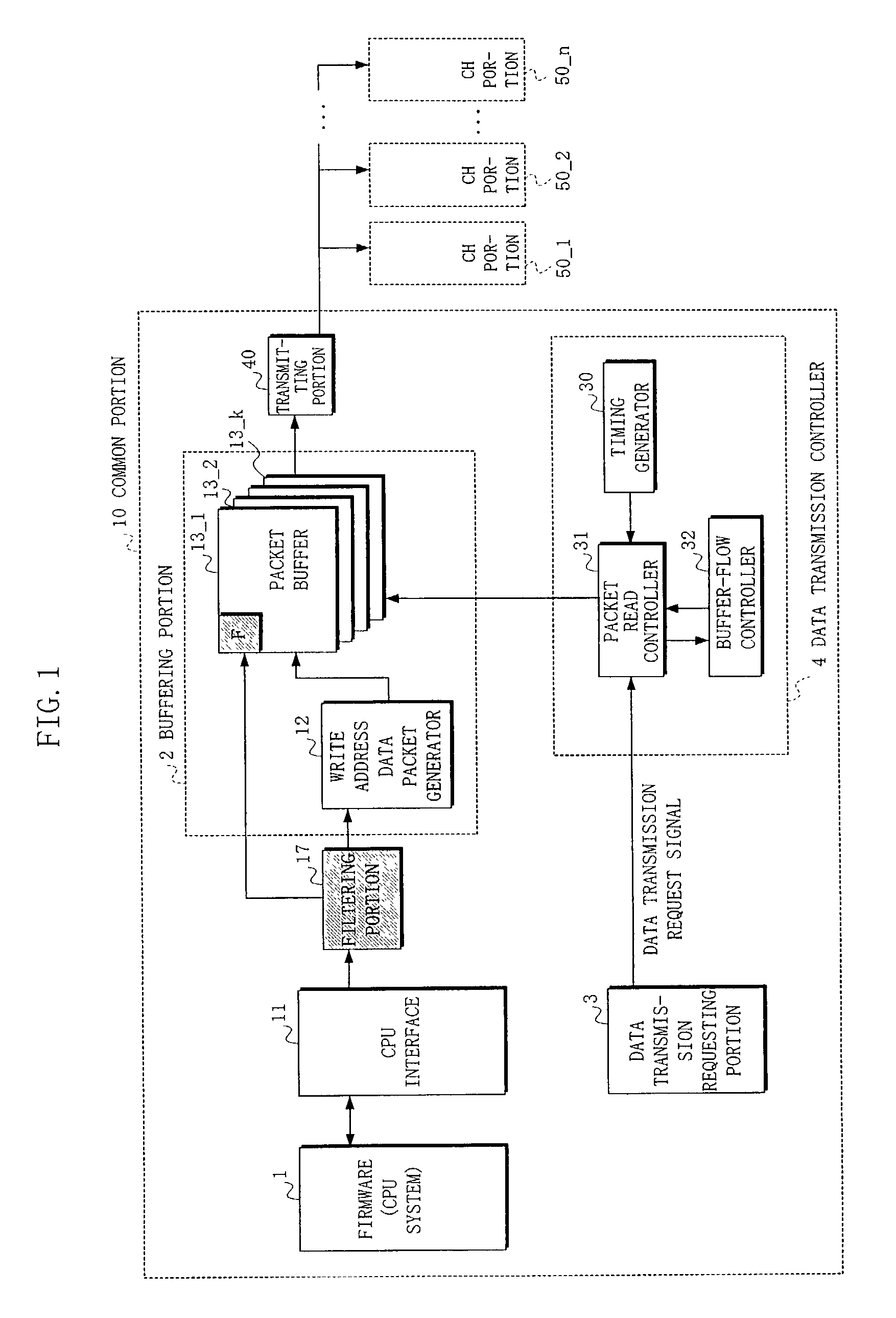
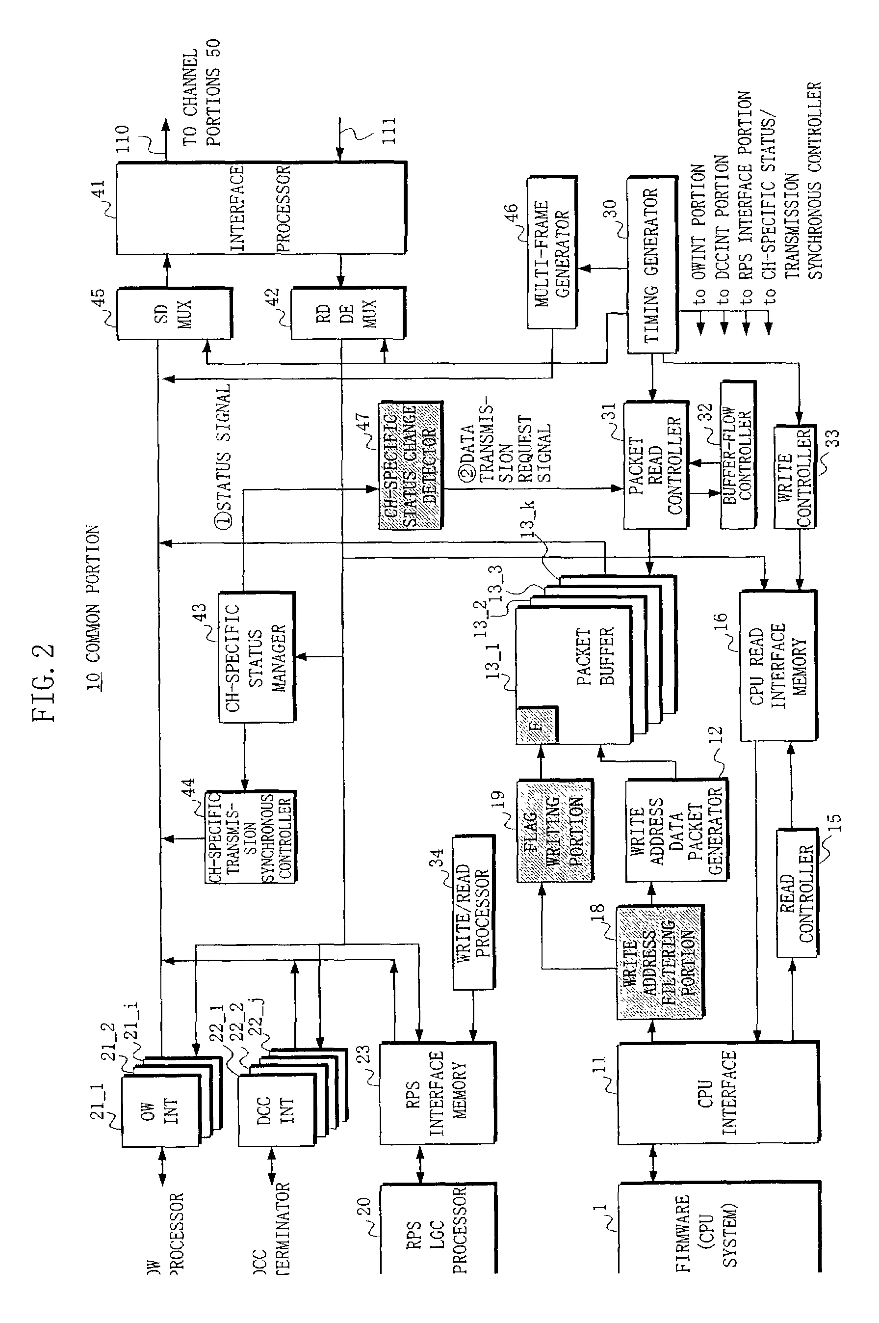
[0138]FIG. 7 shows an arrangement of the common portion 10 in an embodiment (3) of the information transfer equipment according to the present invention. This common portion 10 has, in addition to the arrangement of the common portion 10 in the prior art information transfer equipment shown in FIG. 10, the write address filtering portion 18, the information setting flag writing portion 19, and an address portion switching circuit 49, all shown with hatching.

[0139]In FIG. 7, upon executing a switchover from a working channel portion to a standby channel portion, the RPS LGC processor 20 firstly transmits a standby channel setting change request {circle around (3)} to the packet read controller 31 and the address portion switching circuit 49.

[0140]Since the standby channel setting change request {circle around (3)} includes a working channel number of the switchover source and a standby channel number, the packet read controller 31 transmits the system setting information of the wor...


PUM


Abstract

In an information transfer equipment which executes a monitoring control of a channel portion by transmitting / receiving monitoring control information between the channel portion and a common portion, the common portion stores predetermined information in conjunction with a flag indicating the predetermined information in a buffering portion, and transmits the predetermined information having the flag from the buffering portion when the data transmission of the predetermined information is required.

Description

[0001]This application is a continuation of international application number PCT JP00 / 00541, filed Feb. 1, 2000.BACKGROUND OF THE INVENTION[0002]1. Field of the Invention[0003]The present invention relates to an information transfer equipment, and in particular to an information transfer equipment which executes a monitoring control of a channel portion by transmitting / receiving monitoring control information between the channel portion and a common portion.[0004]2. Description of the Related Art[0005]In recent years, a communication system has aimed at a high transmission capacity and an enhanced monitoring control function regardless of its kind, resulting in an enlarged hardware scale. In a system accomplishing the monitoring control function, it is important that an information transfer equipment works efficiently on the aspects of function and cost.[0006]Generally, an information transfer equipment mounts thereon a microprocessor (CPU) and performs its main function with firmwa...

Claims


Application Information

Patent Timeline
Patent Type & Authority Patents(United States)
IPC IPC(8): H04L12/16H04L12/56H04J3/14H04L12/26H04Q11/04
CPCH04J3/14H04L12/2602H04L43/00H04J2203/006H04L43/0817
Inventor HAZAMA, HISAMICHI
Owner FUJITSU LTD
Why Eureka
Try Eureka