A vehicle brake system

Active Publication Date: 2018-06-21
VOLVO CONSTR EQUIP
View PDF5 Cites 2 Cited by
  • Summary
  • Abstract
  • Description
  • Claims
  • Application Information

AI Technical Summary

Benefits of technology

[0031]characterised by draining the service brake circuit in th

Problems solved by technology

However, this is not possible on a series electric hybrid driveline or an electric driveline with electric hub motors.
Where service brake and parking brake functions share brake assemblies, if the service brake is applied while the parking brake is applied as well, there could be a risk that the brake assembly becomes overloaded due to the combined forces from the service brake circuit and the parking brake circuit.
This could result is damages to the brake assemblies.
For example the friction material of the brake discs can be overloaded, which in turn may damage the friction material.
A problem wit

Method used


Image

  • A vehicle brake system
  • A vehicle brake system
  • A vehicle brake system

Examples


Example

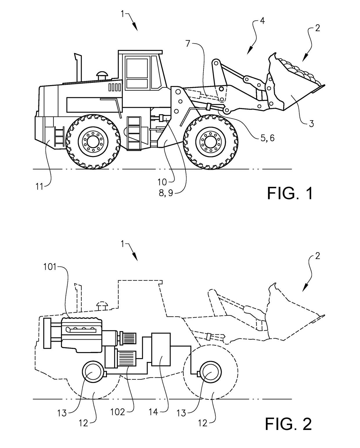
[0046]FIG. 1 is an illustration of a working machine 1 in the form of a wheel loader. The wheel loader is an example of a working machine where a vehicle brake system according to a suitable embodiment of the invention can be applied.

[0047]The wheel loader 1 has an implement 2. The term “implement” is intended to comprise any kind of tool controlled by hydraulics, such as a bucket, a fork or a gripping tool. The implement 2 illustrated in FIG. 1 is a bucket 3 which is arranged on a load arm 4 for lifting and lowering the bucket 3. Further the bucket can be tilted relative to the load arm. In the example illustrated in FIG. 1, a hydraulic system of the wheel loader 1 comprises two hydraulic cylinders 5, 6 for the operation of the load arm 4 and one hydraulic cylinder 7 for tilting the bucket 3 relative to the load arm.

[0048]The hydraulic system of the wheel loader further comprises two hydraulic cylinders 8, 9, steering cylinders, arranged on opposite sides of the wheel loader 1 for ...


PUM


Abstract

The invention provides a vehicle brake system including
    • a brake assembly providing a service brake and a parking brake having a brake disc assembly in common,
    • a service brake circuit,
    • a parking brake circuit, and
    • a brake control arrangement adapted to control the service brake by selectively providing a fluid communication between a pressurising arrangement and the service brake via the service brake circuit, the brake control arrangement further being adapted to control the parking brake by selectively providing a fluid communication between the pressurising arrangement and the parking brake via the parking brake circuit, and by selectively draining the parking brake circuit,
    • wherein the vehicle brake system includes a draining circuit adapted to drain the service brake circuit to avoid overload of the brake disc assembly.

Description

BACKGROUND AND SUMMARY[0001]The invention relates to a vehicle brake system comprising a brake assembly providing a service brake and a parking brake having a brake disc assembly in common. The invention also relates to a working machine, a method for controlling a vehicle brake system, a computer program, a computer readable medium, and a controller for a vehicle brake system.[0002]A working machine, e.g. a wheel loader or an articulated hauler, is usually provided with a bucket, container or other type of implement for digging, carrying and / or transporting a load.[0003]For example, a wheel loader has a lift arm unit for raising and lowering an implement, such as a bucket. The lift arm comprises hydraulic cylinders for movement of a load arm and the implement attached to the load arm. Usually a pair of hydraulic cylinders is arranged for raising the load arm and a further hydraulic cylinder is arranged for tilting the implement relative to the load arm.[0004]In addition, the workin...

Claims


Application Information

Patent Timeline
IPC IPC(8): B60T13/20B60T13/22B60T13/66B60T13/68B60T17/02
CPCB60T13/20B60T13/22B60T13/662B60T13/686B60T17/02B60T13/261B60T13/683
Inventor ABRAHAMSSON, JOHAN
Owner VOLVO CONSTR EQUIP
Why Eureka
Try Eureka