Post-tensioning prestress type self-centering steel frame structure

A post-tensioning, steel frame technology, applied in building components, building structures, earthquake-proof, etc., can solve problems such as tension cracking, uncoordinated lateral deformation of floor and frame, and achieve the effect of avoiding tension cracking.

Active Publication Date: 2014-07-16
SOUTHEAST UNIV
View PDF7 Cites 13 Cited by
  • Summary
  • Abstract
  • Description
  • Claims
  • Application Information

AI Technical Summary

Problems solved by technology

[0005] Technical problem: The present invention aims at the problem that the lateral deformation of the floor and the frame is uncoordinated when the existing self-centering steel frame structure is subjected to an earthquake, and provides a method that not only keeps the column distance constant during the lateral deformation of the columns , to overcome the problem of tensile cracking caused by the inconsistency between the deformation of the floor and the frame, and to flexibly and independently regulate the strength, stiffness and ductility of the structure during the design process, so as to improve the economy of the structure Post-tensioned prestressing self-centering steel frame structure

Method used


Image

  • Post-tensioning prestress type self-centering steel frame structure
  • Post-tensioning prestress type self-centering steel frame structure
  • Post-tensioning prestress type self-centering steel frame structure

Examples


Embodiment Construction

[0035] The technical solution of the present invention will be described in detail below in conjunction with the accompanying drawings.

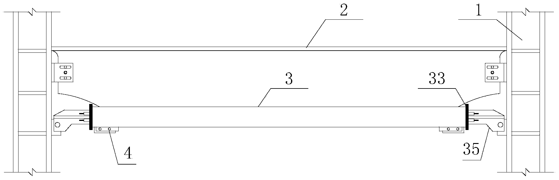
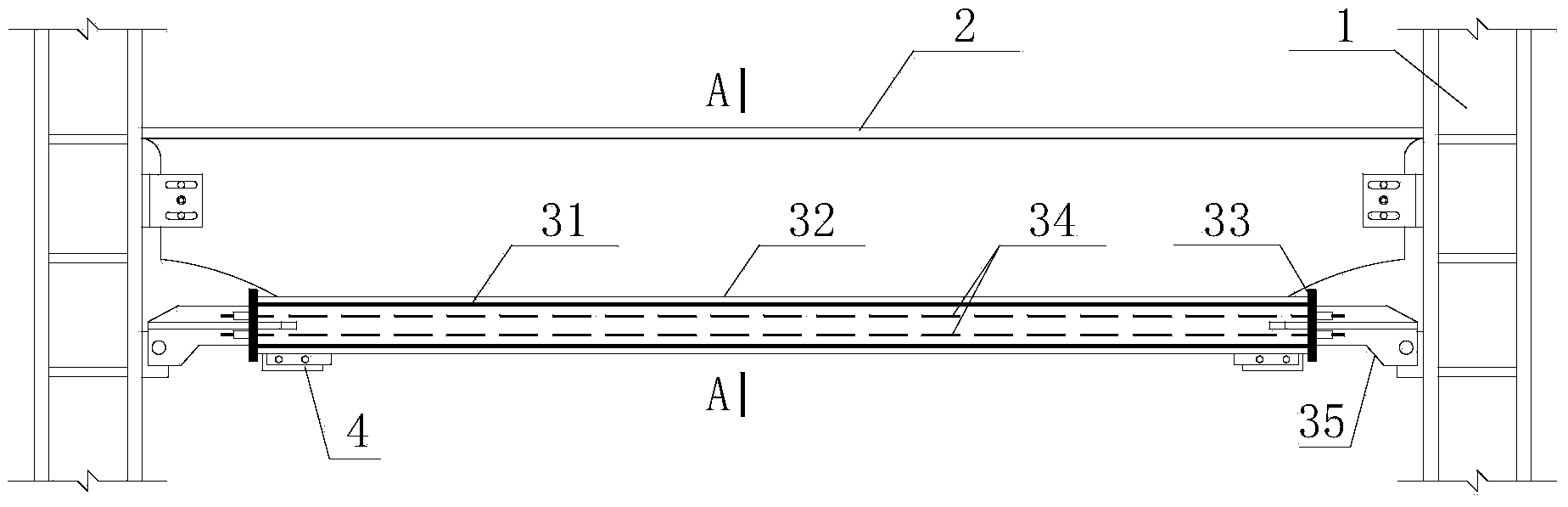
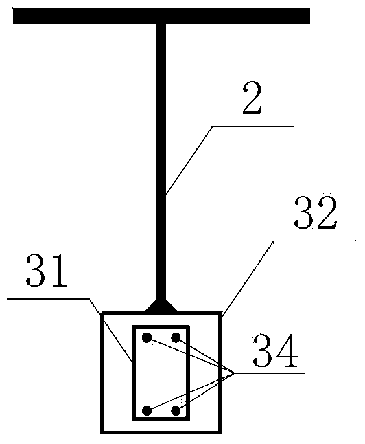
[0036] Such as figure 1As shown, the post-tensioned prestressed self-centering steel frame structure of the present invention includes at least one structural unit, and each structural unit includes two steel frame columns 1, a T-shaped steel beam 2 connecting the upper ends of the two steel frame columns 1, The self-centering connecting piece 3 located on the lower side of the T-shaped steel beam 2 and connecting two steel frame columns 1, the frictional energy-dissipating part 4 located under the self-centering connecting piece 3, wherein the T-shaped steel beam 2 is connected with the self-centering Part 3 and steel frame column 1 are connected by hinges, so as to avoid plastic hinges at the beam-column joints when the structure undergoes lateral deformation; the length of the upper flange of T-shaped steel beam 2 is greater than the leng...


PUM


Abstract

The invention discloses a post-tensioning prestress type self-centering steel frame structure. The post-tensioning prestress type self-centering steel frame structure comprises at least one structural unit. Each structural unit comprises two steel frame columns, a T-shaped steel beam, a self-centering connecting piece and friction energy consumption parts, wherein the T-shaped steel beam is used for connecting the upper ends of the steel frame columns, the self-centering connecting piece is located on the lower side of the T-shaped steel beam and used for connecting the steel frame columns, and the friction energy consumption parts are located on the lower portion of the self-centering connecting piece. Each self-centering connecting piece comprises an inner sleeve, an outer sleeve, end plates, pretensioning rods and connectors, wherein the inner sleeve is sleeved with the outer sleeve, the end plates are located at the two ends of the sleeves, the pretensioning rods are arranged in the inner sleeve and anchored on the end plates, and the connectors are connected with the ends of the inner sleeve. Each friction energy consumption part comprises an inner friction plate, an outer friction plate and a friction gasket, wherein the inner friction plate is connected with the inner sleeve, the outer friction plate is connected with the lower side face of the outer sleeve, the friction gasket is arranged between the inner friction plate and the outer friction plate, and the sliding direction of the inner friction plate and the sliding direction of the outer friction plate are arranged in the axial direction of the outer sleeve. Column space is kept unchanged when the columns are laterally deformed, and the strength, the rigidity and the ductility of the structure can be flexibly and independently adjusted and controlled in the design process.

Description

technical field [0001] The invention belongs to the field of civil engineering and relates to a post-tensioned prestressed self-centering steel frame structure for reducing earthquake disasters of engineering structures. Background technique [0002] Earthquakes bring extremely serious disasters to human beings. The traditional seismic design adopts the ductility design method, that is, under the action of an earthquake, through the early yield and failure of some structural components, but the overall function will not be lost, relying on the plastic deformation of the components to dissipate most of the seismic energy, so as to achieve The purpose of ensuring the safety of the main structure. [0003] Self-centering steel frame structure is a structural form that provides lateral stiffness and self-centering force for the structure by tensioning pre-tensioned rods, and dissipates seismic energy by installing various types of energy-dissipating components. In the traditio...

Claims


Application Information

Patent Timeline
Patent Type & Authority Applications(China)
IPC IPC(8): E04B1/24E04B1/98E04B1/58
Inventor 谢钦周臻孟少平李德猛吴京王春林王维影
Owner SOUTHEAST UNIV
Why Eureka
Try Eureka