
Fat measurement circuit and body fat scale
A circuit and resistance testing technology, applied in diagnostic recording/measurement, medical science, sensors, etc., can solve problems such as poor reference, error, fat rate distortion, etc.
- Summary
- Abstract
- Description
- Claims
- Application Information
AI Technical Summary
Problems solved by technology
Method used
Image

Examples
Embodiment Construction
[0044] The present invention will be further described below in conjunction with the accompanying drawings.
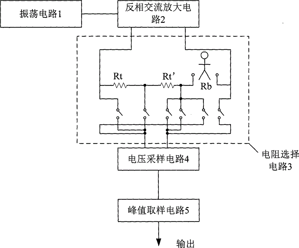
[0045] Such as figure 1 As shown, the fat measuring circuit of the present invention includes an oscillating circuit 1 , an inverting AC amplifier circuit 2 , a resistance selection circuit 3 , a voltage sampling circuit 4 and a peak sampling circuit 5 .
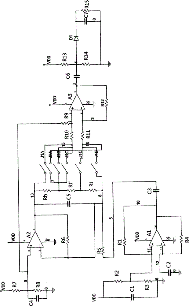
[0046] The oscillation circuit 1 is used to output an AC signal of a certain waveform and frequency, including a first resistor R1, a second resistor R2, a third resistor R3, a fourth resistor R4, a first operational amplifier A1, a first capacitor C1, and a second capacitor C2 and the third capacitor C3. The first resistor R1 is connected between the positive input terminal and the output terminal of the first operational amplifier A1; the fourth resistor R4 is connected between the negative input terminal and the output terminal of the first operational amplifier A1; the second resistor R2 and the third resistor R...
PUM
 Abstract
Description
Claims
Application Information