Device for detecting pins of liquid crystal display panel automatically

An automatic detection device and liquid crystal display technology, applied in the direction of measuring devices, measuring electricity, measuring electrical variables, etc., can solve problems such as differences in test angles of view, misjudgment of lack of display, misjudgment of lack of picture, etc., to achieve detection accuracy , The judgment is simple and intuitive, and the effect of avoiding human influence

CN104090180APending Publication Date: 2014-10-08HEFEI CHENGHUI ELECTRONICS
5 Cites 5 Cited by

Patent Information

Authority / Receiving Office
CN · China
Patent Type
Applications(China)
Current Assignee / Owner
Publication Date
2014-10-08

Smart Images

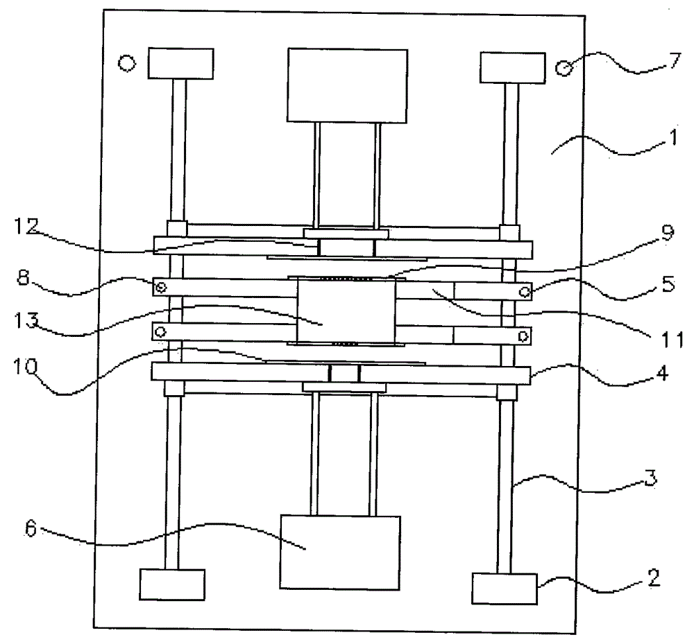
  • Figure 1
    Figure 1
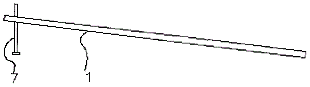
  • Figure 2
    Figure 2
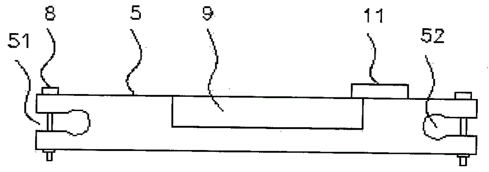
  • Figure 3
    Figure 3
Patent Text Reader

Abstract

The invention relates to a device for detecting pins of a liquid crystal display panel automatically. The device for detecting the pins of the liquid crystal display panel automatically comprises a base plate and air cylinders, wherein positioning columns are fixed to the four corners of the base plate, adjustment screws are connected to the two sides of one end of the bottom surface of the base plate in a threaded mode, a guide rod is arranged between every two adjacent positioning columns in the longitudinal direction, two movable testing plates and two fixed testing plates are arranged between the guide rods on the two sides in a moving and penetrating mode, the two fixed testing plates are arranged between the two movable testing plates, the two the side faces of the two movable testing plates are connected to the air cylinders, the two fixed testing plates are fixed to the guide rods through fastening bolts arranged on the two sides of the fixed testing plates, a testing circuit board is arranged on the side face, near to the corresponding movable testing plate, of each fixed testing plate, a limiting clamping plate is arranged on the upper surface of each fixed testing plate, quantitative labels are arranged on the upper surfaces of the movable testing plates, the number of the quantitative labels corresponds to the number of the pins of the liquid crystal display panel, and the overall width of the quantitative labels corresponds to the overall width of the pins of the liquid crystal display panel. The device for detecting the pins of the liquid crystal display panel automatically is suitable for liquid crystal display panels in different specifications, the visual angle can be adjusted and detected automatically, and detection precision, the detection reliability and the detection timeliness can be improved easily.
Need to check novelty before this filing date? Find Prior Art

Description

technical field

[0001] The invention relates to the technical field of liquid crystal display detection, in particular to an automatic detection device for liquid crystal display pins. Background technique

[0002] In the prior art, the pin detection of the liquid crystal display screen is still manually operated. First, the circuit board is placed flat and pasted on the flat plate on the desktop, and then conductive strips are pasted on the circuit. The inspector manually holds the LCD screen and presses the pins on the conductive strip, and manually moves the LCD screen up, down, left, and right to find the corresponding position for judgment and detection. Its test accuracy, reliability and timeliness are poor, resulting in the following specific problems in the test process:

[0003] (1) During the detection process, the top of the needle tip is in contact with the conductive strip. As time goes by, the physical strength of the testing personnel decreases, resulting in ...

Examples

Embodiment Construction

[0023] In order to make the object, technical solution and advantages of the present invention clearer, the present invention will be further described in detail below in conjunction with the accompanying drawings and embodiments. It should be understood that the specific embodiments described here are only used to explain the present invention, not to limit the present invention.

[0024] In describing the present invention, it should be understood that the terms "longitudinal", "transverse", "upper", "lower", "front", "rear", "left", "right", "vertical", The orientations or positional relationships indicated by "horizontal", "top", "bottom", "inner", "outer", etc. are based on the orientations or positional relationships shown in the drawings, and are only for the convenience of describing the present invention, rather than indicating or It should not be construed as limiting the invention by implying that a referenced device or element must have a particular orientation, be...