shaft drive foldable bicycle

A folding bicycle and shaft transmission technology, applied in the field of transportation, can solve the problems of loss of wheel rotation, heavy, inconvenient to carry, etc., to achieve the effect of reducing the failure rate, reducing the loss rate, and occupying a small area

Active Publication Date: 2016-05-18
平湖岳氏车业股份有限公司
View PDF6 Cites 0 Cited by
  • Summary
  • Abstract
  • Description
  • Claims
  • Application Information

AI Technical Summary

Problems solved by technology

[0003] The purpose of the present invention is to solve the problem that most of the existing folding bicycles are driven by chains and can only be folded once in the middle of the frame; after folding, the two wheels are joined together, and the rotation function of the wheels is lost, which is very inconvenient and heavy to carry around. problem, providing a shaft drive collapsible bicycle

Method used


Image

  • shaft drive foldable bicycle
  • shaft drive foldable bicycle
  • shaft drive foldable bicycle

Examples


specific Embodiment approach 1

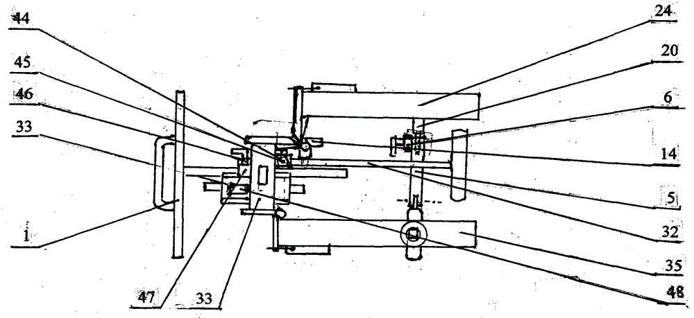
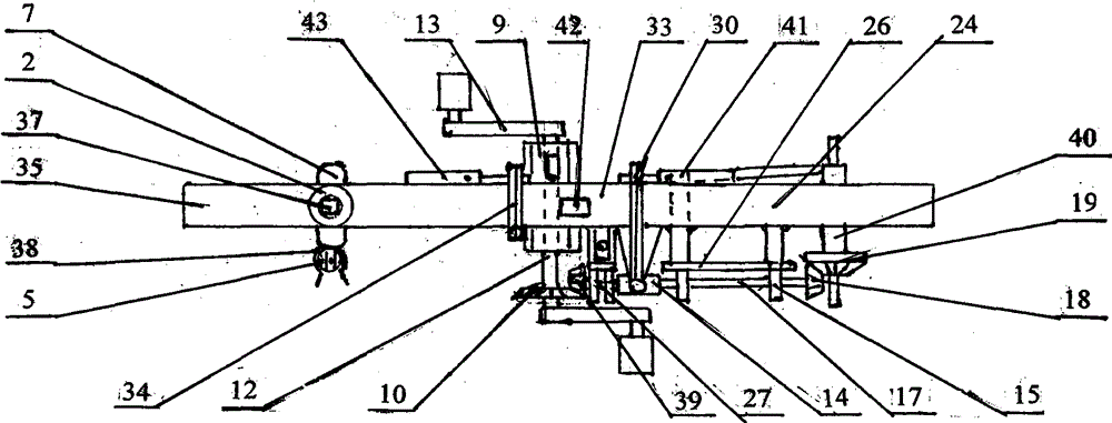
[0006] Specific implementation mode one: (see Figure 1 to Figure 6 ) This embodiment consists of a handlebar assembly 1, a rotating and fixing device 2, an outer circle and an inner square rotating tube 4, a front fork 7, a front wheel assembly 8, a central axis bracket 9, a middle bevel gear 10, and a central axis 12 , large crutch pedal assembly 13, universal joint 14, rear wheel assembly 16, rear drive shaft 17, rear drive shaft bevel gear 18, buckle flywheel and bevel gear assembly 19, rear fork 21, rear Frame 24, front drive shaft 27, rear widened and reinforced hinge 30, seat assembly 32, middle frame 33, front hinge 34, front frame 35, front drive shaft bevel gear 39, rear axle assembly 40. Rear tightening lock 41, front tightening lock 43; it is characterized in that the front interior of the front frame 35 is provided with a rotating and fixing device 2, and the outer circle and inner square rotating tube 4 is arranged inside the rotating and fixing device 2, The up...

specific Embodiment approach 2

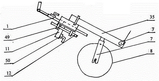
[0007] Specific implementation mode two: (see Figure 1 to Figure 5 ) The difference between this embodiment and the specific embodiment one is that the front end of the front frame 35 and the rear end of the rear frame 24 are respectively provided with luggage racks 3 that can be lifted, and a handlebar is provided inside the central axis bracket 9. Assembly slanting pipe 48, the lower end of the handlebar assembly 1 is inserted into the handlebar assembly slanting pipe 48, fixed by the handlebar assembly slanting fixing device 51 arranged outside the central axis bracket 9, the center axis support 9 The bottom is fixed with the universal wheel insertion tube 11, and the universal wheel insertion tube 11 is inserted into the universal wheel insertion tube 11, and is fixed by the universal wheel fixing device 50 arranged on the universal wheel insertion tube 11 outside. Other compositions and connection methods are the same as those in Embodiment 1.

specific Embodiment approach 3

[0008] Specific implementation mode three: (see Figure 1 to Figure 6 ) The difference between this embodiment and the second embodiment is that the rear two sides of the rear frame 24 are fixed with shelf shaft tubes 25, the two ends of the movable shelf 23 are inserted into the shelf shaft tube 25, and one end of the shelf pole 53 is inserted into In the shelf branch pipe 22, the other end of the shelf pole 53 is movably fixed on the outside of the movable shelf 23, and the outside of the movable shelf 23 is fixed with a shelf pole fixing buckle 55 in addition, and the external setting of the reverse flywheel and bevel gear assembly 19 A gear cover 54 is provided. Other compositions and connection methods are the same as those in the second embodiment.


PUM


Abstract

The invention relates to transportation means, in particular to a shaft drive type foldable bicycle. The shaft drive type foldable bicycle aims to solve the problems that chain drive is adopted in most of existing foldable bicycles, only the middle portions of frames can be folded once, two wheels lose the rotating effect when combined together after folding and the bicycles are inconvenient to carry about and heavy. The shaft drive type foldable bicycle has the advantages that shaft drive decreases the failure rate of chain drive, and the rotating effect of the wheels is fully exerted by folding the bicycle twice; a user can pull the bicycle and will not feel that the bicycle is heavy when carrying the bicycle about, after being folded, the bicycle can be placed vertically and stably, only occupies a small space and can be conveniently taken into a public transportation means or a room, and the losing rate is effectively decreased; the bicycle has the functions of a luggage cart and a goods cart through slight change of the installation mode. The bicycle improves the use efficiency and brings convenience to green travel of people.

Description

technical field [0001] The invention relates to a vehicle, in particular to a shaft-driven foldable bicycle. Background technique [0002] Most of the existing folding bicycles are driven by chains, and can only be folded once in the middle of the vehicle frame; after folding, the two wheels are joined together, and the rotation function of the wheels is lost, so it is very inconvenient and heavy to carry. Contents of the invention [0003] The purpose of the present invention is to solve the problem that most of the existing folding bicycles are driven by chains and can only be folded once in the middle of the frame; after folding, the two wheels are joined together, and the rotation function of the wheels is lost, which is very inconvenient and heavy to carry around. The problem is to provide a shaft-driven foldable bicycle. The present invention includes a handlebar assembly 1, a rotating and fixing device 2, an outer circle and an inner square rotating tube 4, a front...

Claims


Application Information

Patent Timeline
Patent Type & Authority Patents(China)
IPC IPC(8): B62K15/00
Inventor 宋大伟
Owner 平湖岳氏车业股份有限公司
Why Eureka
Try Eureka