Foldable shaft-driven electric bicycle

A technology for folding bicycles and electric bicycles, applied in the field of transportation, can solve the problems of losing the rotation of the wheels, cannot be folded, heavy weight, etc., and achieves the effect of improving the use efficiency, reducing the loss rate, and small footprint

Active Publication Date: 2016-02-17
NEW ENERGY VEHICLE CO LTD OF HANDAN OCEAN IND GRP
View PDF7 Cites 3 Cited by
  • Summary
  • Abstract
  • Description
  • Claims
  • Application Information

AI Technical Summary

Problems solved by technology

[0003] The purpose of the present invention is to solve the problem that most of the existing electric bicycles are large in size, heavy in weight, and cannot be folded. Most of the riding parts of electric bicycles are driven by chains. The wheels are combined together, and the rotation effect of the wheels is lost, and it is very inconvenient and heavy to carry; it is difficult to bring indoors, let alone in shopping malls and public transportation. A shaft-driven foldable electric bicycle is provided.

Method used


Image

  • Foldable shaft-driven electric bicycle
  • Foldable shaft-driven electric bicycle
  • Foldable shaft-driven electric bicycle

Examples


specific Embodiment approach 1

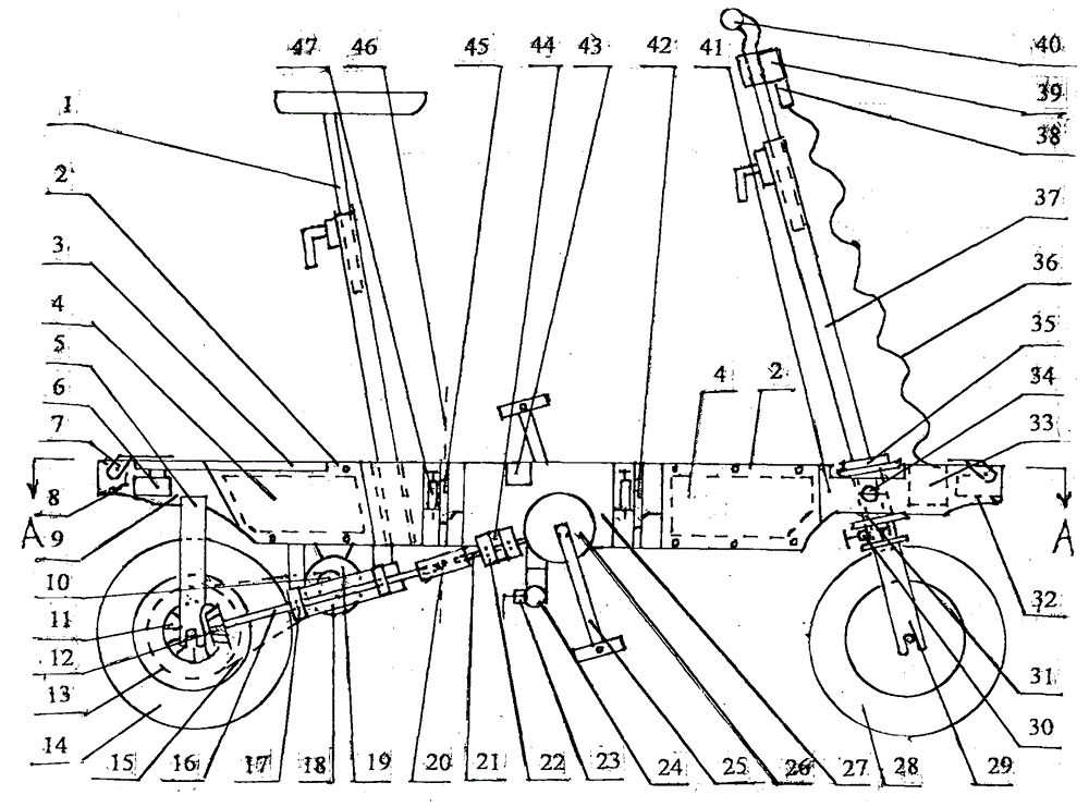
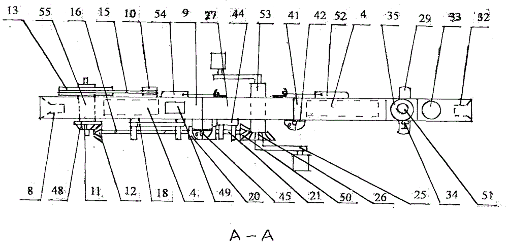
[0006] Specific implementation mode one: (see Figure 1 to Figure 6 ) The present embodiment consists of a vehicle seat assembly 1, a battery cover plate 2, a shelf 3, a battery pack 4, a rear fork 5, a rear right turn signal 6, a movable luggage rack 7, a taillight 8, a rear frame 9, a small Pulley 10, rear bevel gear a11, rear bevel gear b12, large pulley 13, rear tire 14, belt 15, rear drive shaft 16, rear bearing assembly 17, rear bearing assembly frame 18, DC motor 19, universal Section 20, front transmission shaft 21, front bearing assembly 22, handlebar placement lock device 23, handlebar placement pipe 24, big turn 25, large bevel gear 26, middle frame 27, front wheel assembly 28, front Fork assembly 29, handlebar locking device 30, fixing pipe 31, front lamp 32, spiral wire box 33, front fork locking device 34, front fork rotating assembly 35, spiral wire 36, handlebar assembly 37. Plug 38, wiring display box and socket 39, speed control handlebar cover 40, front fra...

specific Embodiment approach 2

[0007] Specific implementation mode two: (see Figure 1 to Figure 5) The difference between this embodiment and the first embodiment is that a movable shaft 58 is provided at the front part between the bracket 57 and the handlebar placement tube 24, and an angle adjuster 59 is provided at the rear part between the bracket 57 and the handlebar placement tube 24 , the angle regulator 59 is provided with an angle locking device 60, the bottom of the middle frame 27 is provided with a universal wheel intubation 61, and the universal wheel intubation 61 is provided with a universal wheel locking device 62, and the universal wheel 63 Insert the upper end of the universal wheel in the inserting tube 61. Place the handlebar assembly 37 horizontally, lift the movable luggage rack 7, realize the function of the luggage cart, install and fix the universal wheel 63, adjust the angle of the handlebar assembly 37, and realize the function of pulling the truck. Other compositions and connec...

specific Embodiment approach 3

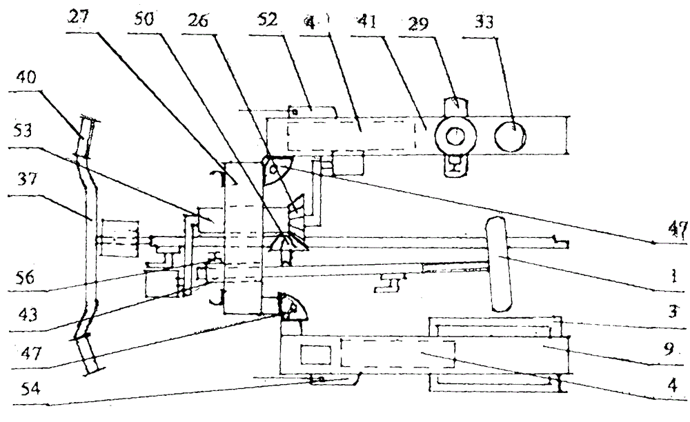
[0008] Specific embodiment three; (see Figure 1 to Figure 7 ) The difference between this embodiment and the second embodiment is that the middle part of the front hinge 42 and the rear hinge 45 is provided with a 90-degree automatic lock 47, and the 90-degree fan-shaped orifice plate 68 is fixed on the front hinge 42 and the rear hinge. The left middle part of 45 and the right middle part are fixed with fan-shaped curved orifice plate 70, the shell 71 is fixed on the 90-degree fan-shaped orifice plate 68, the front end of movable pull rod 66 is provided with baffle plate 69, and the upper side of baffle plate 69 is provided with spring 67 . Other compositions and connection methods are the same as those in the second embodiment.


PUM


Abstract

The invention relates to a foldable shaft-driven electric bicycle, which relates to a transportation tool, and aims at solving the problems that an existing electric bicycle is large in size, heavy in weight, incapable of being folded, only capable of being folded in the middle part of a frame for one time since a riding part of the electric bicycle is mostly chain-driven, inconvenient to carry along and heavy since two wheels are arranged side by side after the electric bicycle is folded and lose the rotation effect of the wheels, difficult to bring into a room and incapable of being brought to a shopping mall and a public transportation tool. The foldable shaft-driven electric bicycle has the beneficial effects of being small in size and light in weight, sufficiently playing the rotation function of the wheels after being folded twice, being easy to carry along in a pulling manner, being vertically arranged after being folded, being stable and small in floor occupation area, being convenient to bring into a room, a shopping mall and a public transportation tool and to arrange in a trunk of a car and a cab of a heavy truck and effectively reducing the loss rate; by slightly changing the installation way, a function of a luggage trolley and a cart can be improved. The application efficiency is increased, and convenience is brought to the environment-friendly travel of people.

Description

technical field [0001] The invention relates to a vehicle, in particular to a shaft-driven foldable electric bicycle. Background technique [0002] Most of the existing electric bicycles are large in size and heavy in weight and cannot be folded. The riding part of the electric bicycle is mostly driven by a chain. Even if it is folded, it can only be folded once at the middle part of the vehicle frame. Losing the turning effect of the wheels, it is very inconvenient and heavy to carry; it is difficult to bring indoors, let alone in shopping malls and public transportation. Contents of the invention [0003] The purpose of the present invention is to solve the problem that most of the existing electric bicycles are large in size, heavy in weight, and cannot be folded. Most of the riding parts of electric bicycles are driven by chains. The wheels are combined together, and the rotation effect of the wheels is lost, and it is very inconvenient and heavy to carry; it is diffi...

Claims


Application Information

Patent Timeline
IPC IPC(8): B62K13/00B62K15/00B62M17/00
CPCB62K13/00B62K15/008B62M17/00B62M6/60B62M6/90
Inventor 宋大伟
Owner NEW ENERGY VEHICLE CO LTD OF HANDAN OCEAN IND GRP
Why Eureka
Try Eureka