Gear speed reduction motor

A technology of gear reduction and bevel gear, which is applied in the direction of gear transmission, belt/chain/gear, electrical components, etc., can solve the problems of wasting maintenance time, inconvenient disassembly and assembly, etc., and achieve material cost saving, convenient disassembly and assembly, and small weight Effect

Active Publication Date: 2015-01-07
浙江通宇变速机械股份有限公司
View PDF8 Cites 3 Cited by
  • Summary
  • Abstract
  • Description
  • Claims
  • Application Information

AI Technical Summary

Problems solved by technology

However, the combined gear reduction motor still has great limitations in disassembly and assembly, which is inconvenient to disassemble and waste maintenance time. The applicant hopes to provide a more convenient disassembly and assembly of the gear reduction motor

Method used


Image

  • Gear speed reduction motor
  • Gear speed reduction motor
  • Gear speed reduction motor

Examples


Embodiment 1

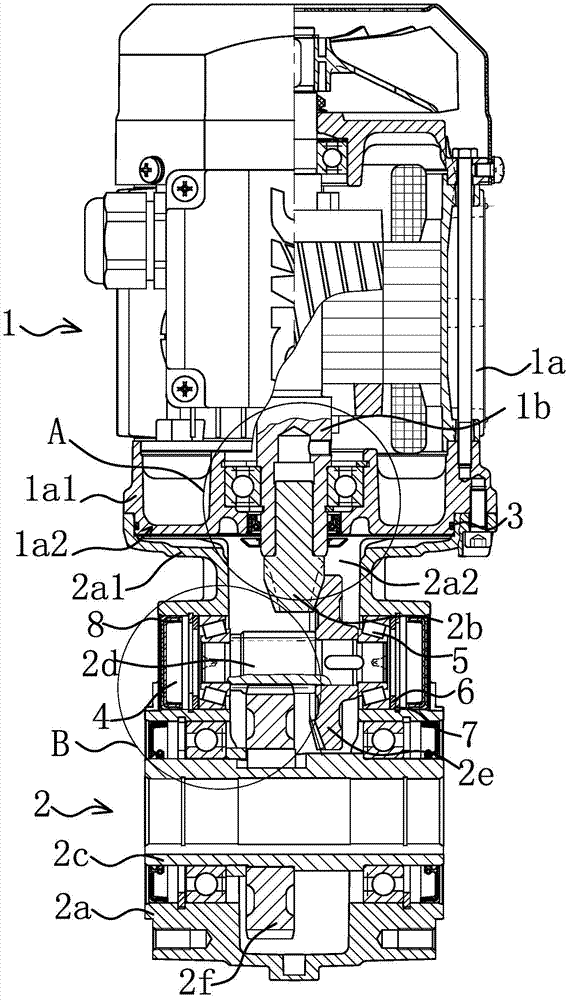
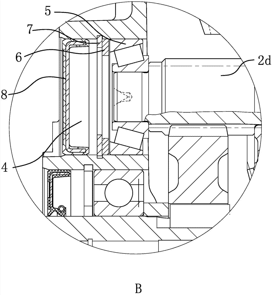
[0040] Such as Figure 1 to Figure 4 As shown, a gear reduction motor includes a motor 1 and a reducer 2; the motor 1 has a motor housing 1a and a motor shaft 1b; the reducer 2 has a casing 2a, a bevel gear input shaft 2b and an output shaft 2c, and the motor The casing 1a is fixedly connected with the box body 2a, the motor shaft 1b is coaxially arranged with the bevel gear input shaft 2b and one end of the motor shaft 1b penetrates into the box body 2a and is fixedly connected with the bevel gear input shaft 2b. The present invention starts from the connection relationship between the motor 1 and the reducer 2, so that one end of the motor shaft 1b directly penetrates into the box 2a and is fixedly connected with the bevel gear input shaft 2b. However, in an ordinary geared motor, the motor shaft 1b usually needs to be connected with the input shaft in the box body 2a through a complex gear connection structure. Compared with ordinary gear reduction motors, this saves the c...

Embodiment 2

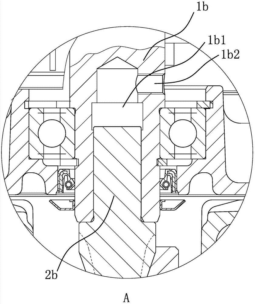
[0050] Such as Figure 5 As shown, the structure and principle of this embodiment are basically the same as those of Embodiment 1, the difference lies in: a shaft hole 1b1 coaxial with the bevel gear input shaft 2b is provided on the shaft end face of the bevel gear input shaft 2b , The motor shaft 1b penetrates into the shaft hole 1b1 and tightly fits with the shaft hole 1b1, so that the same effect can be achieved. And make the shaft hole-1b1 depth of the bevel gear input shaft 2b greater than the length of the motor shaft 1b extending into the shaft hole-1b1, in addition, there is also a hole on the outer surface of the bevel gear input shaft 2b that communicates with the bottom of the shaft hole-1b1 The hydraulic connection hole 1b2. Similarly, threads are provided on the wall of the hydraulic connection hole 1b2 to facilitate screwing in of the hydraulic nozzle.


PUM


Abstract

The invention provides a gear speed reduction motor, belongs to the technical field of machines, and aims to solve the problems that a conventional gear reduction motor is inconvenient to assemble or disassemble and long mounting and repairing time is needed. The gear speed reduction motor of an improved structure comprises a motor and a speed reducer, wherein the motor is provided with a motor shell and a motor rotating shaft; the speed reducer is provided with a box body, a bevel gear input shaft and a bevel gear output shaft; the motor shell is fixedly connected with the box body; the motor rotating shaft and the bevel gear input shaft are arranged in a co-axis manner; one end of the motor rotating shaft penetrates into the box body to be fixedly connected with the bevel gear input shaft; an ejection structure is further arranged between the motor rotating shaft and the bevel gear input shaft; a bevel wheel shaft is arranged between the bevel gear input shaft and the bevel gear output shaft; the bevel wheel shaft is positioned inside the box body and is fixedly connected with a bevel gear which is meshed with the bevel gear input shaft; the bevel gear output shaft is fixedly connected with a bevel wheel which is meshed with the bevel wheel shaft. The gear speed reduction motor of the improved structure is simple and compact in structure and convenient and rapid to assemble and disassemble.

Description

technical field [0001] The invention belongs to the technical field of machinery, and relates to a reduction device, in particular to a gear reduction motor. Background technique [0002] Compared with the general worm gear reducer, the gear reducer has a larger transmission ratio and smaller volume, and the transmission efficiency is much higher. It has a better cost performance than the worm gear reducer, so it is widely used. It is usually combined with a geared motor to achieve the purpose of reducing the speed and increasing the torque. There is no need for couplings and adapters between the two. The structure is compact and the load is evenly distributed on the planetary gears, so the load capacity is relatively high and can meet small spaces. The need for high torque output. [0003] Such as a hypoid gear reducer that is recorded in the Chinese patent literature and is suitable for industrial production (application number: 201320705292.X; authorized announcement num...

Claims


Application Information

Patent Timeline
Patent Type & Authority Applications(China)
IPC IPC(8): H02K7/116F16H1/20
CPCF16H1/203H02K7/116
Inventor 唐礼明徐忠法
Owner 浙江通宇变速机械股份有限公司
Why Eureka
Try Eureka