Illumination device

A lighting device, a progressive technology, applied in the direction of lighting devices, lighting device components, lighting and heating equipment, etc., can solve the problems that the luminous intensity cannot be provided, the light source cannot provide luminous intensity, etc., and achieve the effect of uniform luminous intensity

Inactive Publication Date: 2015-01-14
LITE ON ELECTRONICS (GUANGZHOU) LTD +1
View PDF4 Cites 3 Cited by
  • Summary
  • Abstract
  • Description
  • Claims
  • Application Information

AI Technical Summary

Problems solved by technology

[0002] The light source produced by general light-emitting diodes (LEDs) cannot provide uniform luminous intensity due to different luminous angles
Therefore, how to improve the lack of "the light source produced by general LEDs cannot provide uniform luminous intensity due to different light angles" through the improvement of structural design has become an important issue that people in this business want to solve.

Method used


Image

  • Illumination device
  • Illumination device
  • Illumination device

Examples


no. 1 example 〕

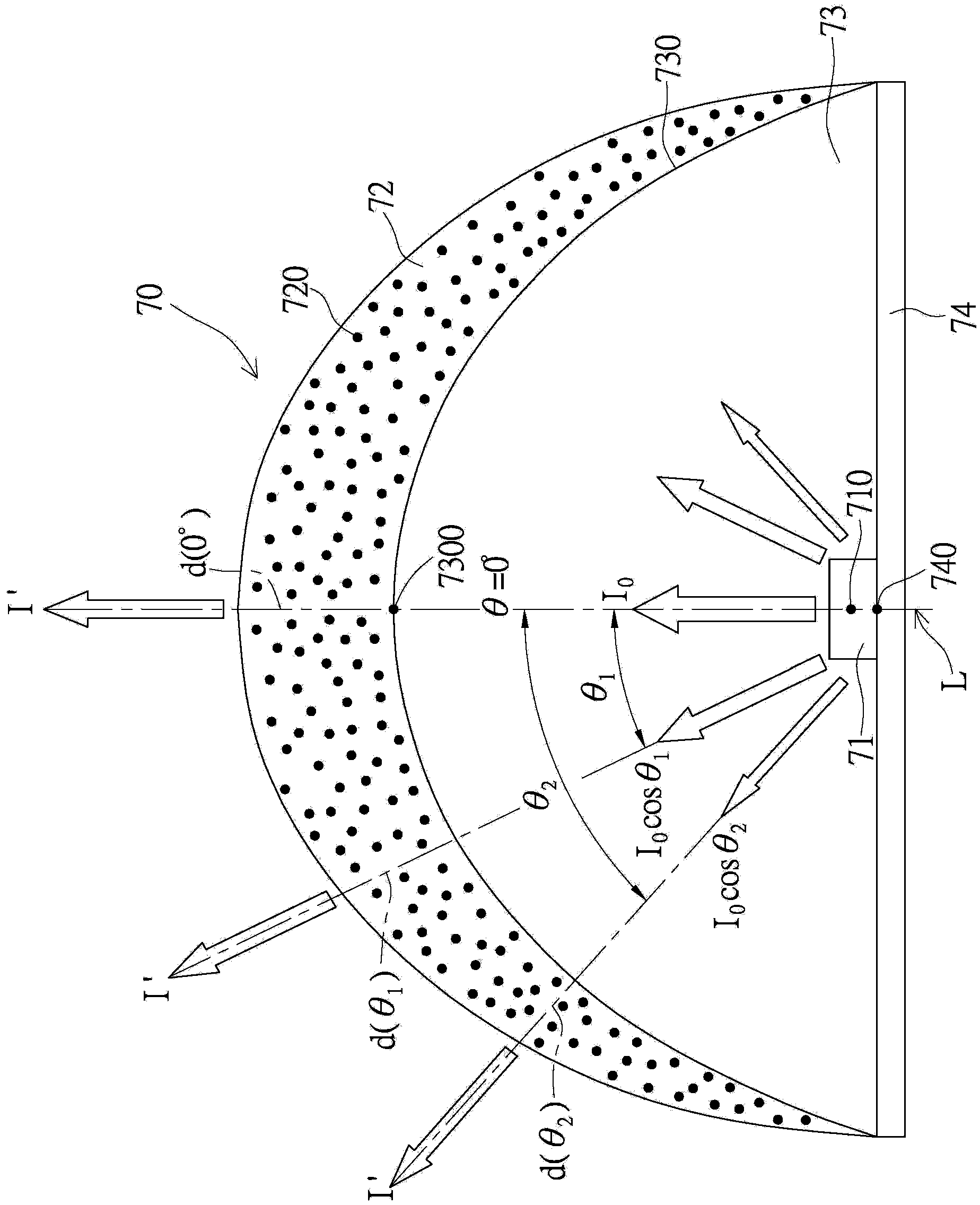
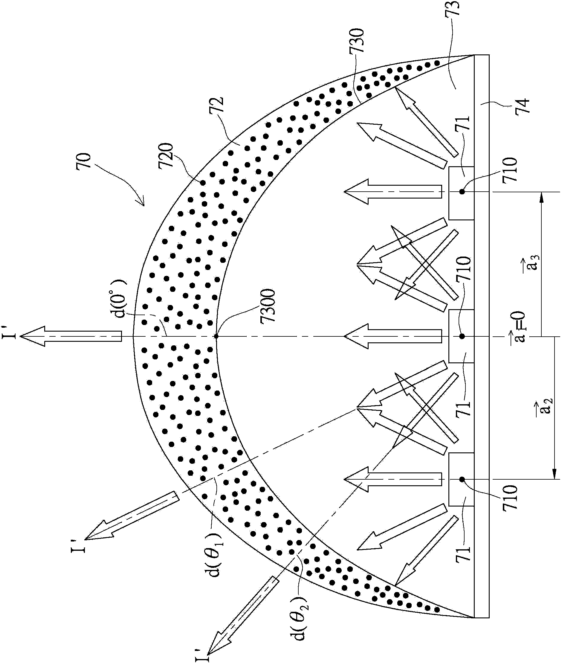
[0045] see Figure 1A As shown, the first embodiment of the present invention provides an illumination device 70 , which includes: a base 74 , at least one photoelectric element 71 , a first layer 73 and a second layer 72 . In this embodiment, only one photoelectric element 71 is used as a light-emitting module, but in different variations of different embodiments, multiple photoelectric elements 71 can also be used as a light-emitting module at the same time, so this embodiment does not use a photoelectric element The number of 71 is used as the limitation of the present invention. Furthermore, the photoelectric element 71 is disposed on the base 74 and is electrically connected to the base 74 for generating a first light with progressive luminous intensity I(θ) (such as Figure 1A Indicated by the arrow projected from the photoelectric element 71 ), and the progressive luminous intensity I(θ) may show a trend of gradually decreasing from the top of the photoelectric element 7...

no. 2 example

[0092] see Figure 2A As shown, the second embodiment of the present invention provides a lighting device 80 using only one photoelectric element 81 as a light emitting module. The illuminating device 80 of the second embodiment is similar to the illuminating device 70 of the first embodiment, and the biggest difference is that the progressive structure adopted by the second embodiment is the progressive concentration of the phosphor powder mixed in the second layer 82 D(θ), same as the first embodiment, also corresponds to the progressive luminous intensity I(θ) of the first light.

[0093] Furthermore, both the progressive luminous intensity I(θ) of the first light and the progressive concentration D(θ) of the phosphor powder in the second layer 82 can simultaneously show an increasing or decreasing trend corresponding to each other ( That is to say, there is a positive correlation between the progressive luminous intensity I(θ) of the first light generated by the photoelec...

no. 3 example

[0127] see Figure 3A As shown, the third embodiment of the present invention provides a lighting device 90 using only one photoelectric element 91 as a light emitting module. The lighting device 90 of the third embodiment is similar to the lighting device 90 of the first and second embodiments, but the biggest difference is that the progressive structure adopted by the third embodiment is the fluorescence of the phosphor powder mixed in the second layer 92 The progressive particle radius R(θ) of the particles 920 is also corresponding to the progressive luminous intensity I(θ) of the first light as in the first and second embodiments.

[0128] Furthermore, there is a correlation between the progressive luminous intensity I(θ) of the first light and the progressive particle radius R(θ) of the phosphor powder in the second layer 92 . For example, when the progressive luminous intensity I(θ) of the first light shows an "increasing" variation trend, the progressive particle radi...


PUM


Abstract

An illumination device includes a base, a light-emitting module, a first layer, and a second layer. The light-emitting module is disposed on the base for generating a progressive-type light-emitting intensity. The first layer encapsulates the light-emitting module. The second layer encloses the first layer. The second layer has a progressive-type thickness corresponding to the progressive-type light-emitting intensity, and both the progressive-type light-emitting intensity and the progressive-type thickness are decreased or increased gradually, thus the progressive-type light-emitting intensity can be transformed into the uniform light-emitting intensity of the second light through the progressive-type thickness of the second layer.

Description

technical field [0001] The present invention relates to a lighting device, in particular to a lighting device that uses a progressive structure to generate a uniformly emitted light source with uniform luminous intensity. Background technique [0002] Generally, light sources generated by light emitting diodes (LEDs) cannot provide uniform luminous intensity due to different luminous angles. Therefore, how to improve the lack of "the light sources produced by general LEDs cannot provide uniform luminous intensity due to different luminous angles" through the improvement of structural design has become an important issue that people in this industry want to solve. Contents of the invention [0003] The object of the present invention is to provide a lighting device, which can generate a uniform emitting light source with uniform luminous intensity by using a progressive structure. [0004] An illumination device provided by one embodiment of the present invention includes:...

Claims


Application Information

Patent Timeline
Patent Type & Authority Applications(China)
IPC IPC(8): H01L33/50
CPCF21V9/16F21K9/56H01L33/50H01L33/507H01L33/508F21V3/02F21S4/28F21K9/232F21K9/64F21Y2115/10F21V9/32
Inventor 吴嘉豪吴俊昌
Owner LITE ON ELECTRONICS (GUANGZHOU) LTD
Why Eureka
Try Eureka