Luminescent glass capable of light control and automatic lightening

Inactive Publication Date: 2018-06-29
UNIV OF ELECTRONICS SCI & TECH OF CHINA
View PDF7 Cites 1 Cited by
  • Summary
  • Abstract
  • Description
  • Claims
  • Application Information

AI Technical Summary

Problems solved by technology

[0006] The purpose of the present invention is to propose a luminous glass that can be light-controlled and automatically lit to solve the problems that the lighting system in the existing intelligent building does not automatically light up according to the change of ambient light intensity to achieve lighting and the light extraction intensity is uneven

Method used


Image

  • Luminescent glass capable of light control and automatic lightening

Examples


Embodiment 1

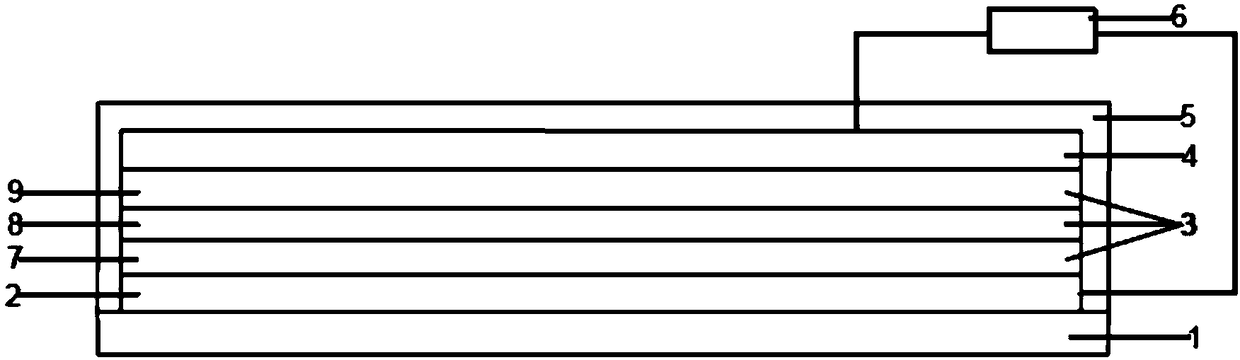
[0027] Such as figure 1 As shown, a light-emitting glass that can be automatically lit by light control includes an ITO glass substrate 1, a transparent conductive material 2, a transparent light-emitting unit 3, a transparent metal electrode 4, a transparent packaging material 5, and a control circuit 6; The material 2 is deposited on the ITO glass substrate 1, the transparent light-emitting unit 3 is provided on the transparent conductive material 2, and the transparent metal electrode 4 is provided on the transparent conductive material 2; the packaging material covers the transparent conductive material Material 2; The control circuit 6 is connected to the transparent metal electrode 4 through the packaging material. The transparent conductive material 2 has good transparency and conductivity, especially has a transmittance of more than 80% and good electron transmission characteristics in the visible light band, and is generally zinc oxide. The transparent conductive mate...

Embodiment 2

[0029] Such as figure 1 As shown, on the basis of Example 1, a light-emitting glass that can be light-controlled and automatically lit includes an ITO glass substrate 1, a transparent conductive material 2, a transparent light-emitting unit 3, a transparent metal electrode 4, a transparent packaging material 5 and The control circuit 6; the transparent conductive material 2 is deposited on the ITO glass substrate 1, the transparent light-emitting unit 3 is provided on the transparent conductive material 2, and a transparent metal electrode 4 is provided on the transparent conductive material 2; The packaging material covers the transparent conductive material 2; the control circuit 6 is connected to the transparent metal electrode 4 through the packaging material. The transparent conductive material 2 has good transparency and conductivity, especially has a transmittance of more than 80% and good electron transmission characteristics in the visible light band, and is generally ...


PUM

PropertyMeasurementUnit
thicknessaaaaaaaaaa
thicknessaaaaaaaaaa
thicknessaaaaaaaaaa

Abstract

The present invention discloses luminescent glass capable of light control and automatic lightening. The glass comprises an ITO glass substrate, transparent conductive materials, a transparent luminescence unit, a transparent metal electrode, transparent packaging materials and a control circuit. The transparent conductive materials are deposited on the ITO glass substrate, the transparent luminescence unit is arranged on the transparent conductive materials, and the transparent conductive materials are provided with the transparent metal electrode; the transparent packaging materials are configured to package the transparent metal electrode, the transparent luminescence unit and the transparent conductive materials on the ITO glass substrate; and the control circuit penetrates the transparent packaging materials and is connected with the transparent metal electrode and the transparent conductive materials. The luminescent glass capable of light control and automatic lightening is accessed into a circuit of reverse voltage supply to generate current signals in the circuit under the ultraviolet irradiation, and the circuit maintains reserve voltage supply. The transparent packagingmaterials have the main functions of avoiding erosion of the transparent conductive materials, the transparent luminescence unit and the transparent metal electrode under a water oxygen environment and avoiding damaging caused by external forces.

Description

Technical field [0001] The invention belongs to the field of luminous glass, and mainly relates to a luminous glass that can be light-controlled and automatically lit. Background technique [0002] Organic light-emitting diodes (OLED) mainly use organic light-emitting small molecules and high molecular polymers as light-emitting materials, and are prepared by evaporation or spraying. At present, OLED lighting products have been mass-produced. The advantages of OLED lighting products are high luminous efficiency, low energy consumption, surface light emission and transparency, making them excellent architectural lighting equipment. [0003] Recently, electroluminescent diodes (LEDs) have been used in lighting systems for buildings, and LED-based lighting glass has also been described. Most of them pass through a double-layer glass sandwich structure. The light emitted by the diode is guided through one or more of the side edges forming the edge surface into a part of the glass form...

Claims


Application Information

Patent Timeline
Patent Type & Authority Applications(China)
IPC IPC(8): H05B33/12H05B33/14
CPCH05B33/12H05B33/145
Inventor 于军胜赵聃王子君侯思辉
Owner UNIV OF ELECTRONICS SCI & TECH OF CHINA
Why Eureka
Try Eureka