Test device and test method for testing kinetic shear characteristics between pipe piles and grouting soil bodies

A test device and test tube technology, which is applied in the direction of using a stable shear force to test the strength of materials, etc., can solve the problems of poor pertinence of test equipment and test methods, difficulty in determining the similarity ratio of test models, and low accuracy. Achieve the effect of avoiding boundary effects, reliable basic data, and accurate test results

Active Publication Date: 2015-02-25
GUANGZHOU INSTITUTE OF BUILDING SCIENCE CO LTD +1
View PDF7 Cites 26 Cited by
  • Summary
  • Abstract
  • Description
  • Claims
  • Application Information

AI Technical Summary

Problems solved by technology

[0004] The purpose of the present invention is to solve the problem that the existing test equipment and test methods are not targeted, the accuracy is not high, the boundary effect of the box wall, the scale effect, the test model, etc. For the technical problem that the

Method used


Image

  • Test device and test method for testing kinetic shear characteristics between pipe piles and grouting soil bodies
  • Test device and test method for testing kinetic shear characteristics between pipe piles and grouting soil bodies
  • Test device and test method for testing kinetic shear characteristics between pipe piles and grouting soil bodies

Examples


Example Embodiment

[0040] The preferred embodiments of the present invention will be described below with reference to the accompanying drawings. It should be understood that the preferred embodiments described here are only used to illustrate and explain the present invention, and are not used to limit the present invention.

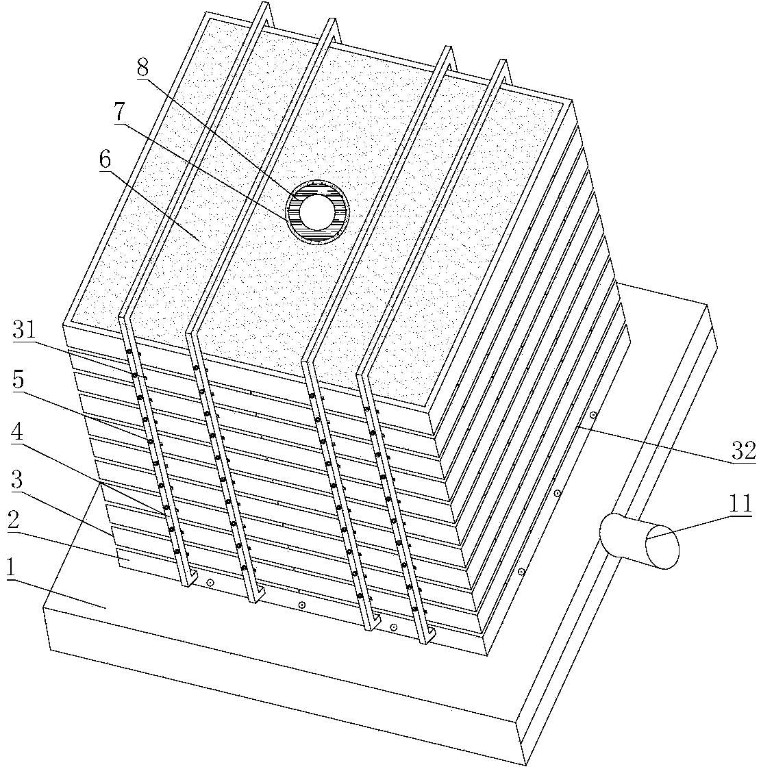
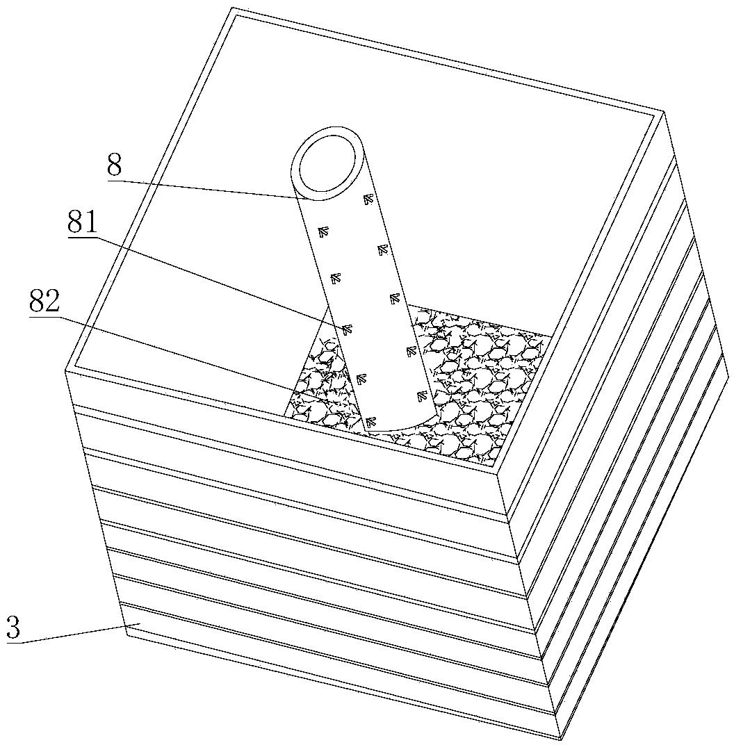
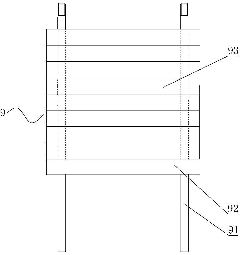
[0041] Such as Figure 1 ~ Figure 6 As shown, the test device for testing dynamic shear characteristics between pipe piles and grouted soil according to the present invention includes a vibration platform 1, a pipe pile model test box set on the vibration platform 1, and a pipe pile loading load The loading mechanism 9 and the monitoring system. In this embodiment, the loading mechanism 9 includes a mass 93, a support frame 91, and a bearing plate 92 for placing the mass 93. The bearing plate 92 is provided with a supporting frame 91 Through the mounting hole 94, the bottom of the support frame 91 is welded and fixed to the end plate of the pipe pile. Four support frames 91 ...


PUM

PropertyMeasurementUnit
Thicknessaaaaaaaaaa

Abstract

The invention discloses a test device and a test method for testing kinetic shear characteristics between pipe piles and grouting soil bodies. The test device comprises a vibration platform, a pipe pile model test box, a loading mechanism and a monitoring system, wherein the pipe pile model test box comprises a steel bottom plate, stacked steel frames, a limiting mechanism, pipe piles arranged in the steel frames, and a sandy oil body; guide chutes are formed between the steel frames; balls are arranged on the guide chutes; hard soil is spread on the steel bottom plate; the part between the pipe piles and the sandy oil body is filled with cement paste; sealing films are arranged on the inner walls of the steel frames; and the monitoring system comprises a displacement sensor, a strain rosette group arranged on the outer surfaces of the pipe piles, and a pressure box arranged in the sandy oil body. According to the device and the method disclosed by the invention, the box wall boundary influence can be well eliminated, the problem that a scale effect and a test model similarity ratio relationship are difficult to determine is solved, the test results are accurate, reasonable and reliable, and reliable basic data is provided for theoretical analysis and engineering practice.

Description

Technical field [0001] The invention belongs to the technical field of civil engineering test devices, and specifically relates to a test device and method for testing dynamic shear characteristics between pipe piles and grouting soil. Background technique [0002] Since my country introduced and used prestressed concrete pipe piles in large quantities, it has not only saved a large amount of various building materials, energy and funds, but also greatly shortened the construction period of the project. Pipe piles are a common foundation form of buildings, mainly used for compressive, pull-out and horizontal resistance of buildings. Because the high-strength pre-stressed concrete pipe pile consumes less building materials, the factory production efficiency is high, the pile quality is good, the strength is high, and it is resistant to construction. Therefore, in recent years, with the rapid development of world economic construction, the concept of energy conservation and enviro...

Claims


Application Information

Patent Timeline
IPC IPC(8): G01N3/24
Inventor 戚玉亮唐孟雄胡贺松
Owner GUANGZHOU INSTITUTE OF BUILDING SCIENCE CO LTD
Why Eureka
Try Eureka