

Tunnel lining non-destructive testing method based on audio frequency analysis
A non-destructive testing and tunneling technology, which is applied in the analysis of materials, the use of sound waves/ultrasonic waves/infrasonic waves to analyze solids, and the use of sound waves/ultrasonic waves/infrasonic waves for material analysis. It can solve the problems of no quantitative standards and low detection accuracy, and achieve scientific detection. , the effect of accurate test results
- Summary
- Abstract
- Description
- Claims
- Application Information
AI Technical Summary
Problems solved by technology
Method used
Image


Examples
Embodiment
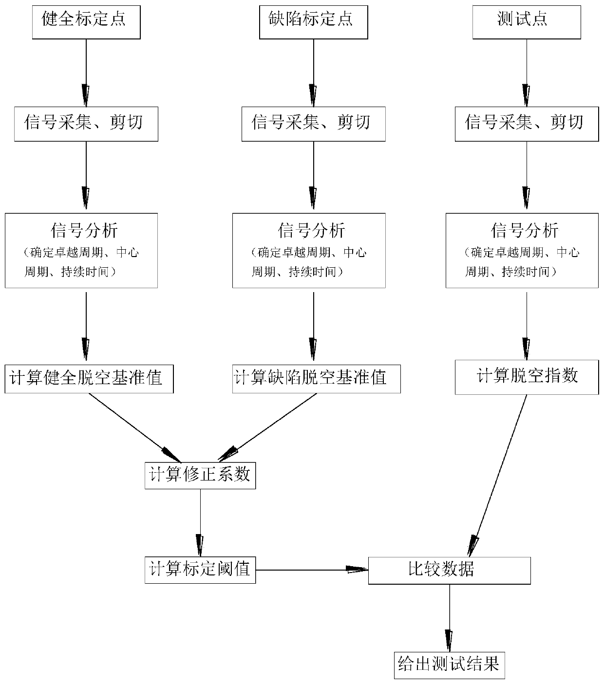
[0027] A tunnel lining non-destructive testing technology based on audio frequency analysis, comprising the following steps:
[0028] A smart phone with audio signal processing software is used to sample the percussion audio frequency generated by the exciter hammer striking the tunnel lining at a given sampling frequency to obtain the tunnel lining percussion audio signal; the percussion audio signal includes the exciter The ambient audio signal before the vibrating hammer is struck, and the audio signal after the vibrating hammer is struck. It should be noted that the mobile terminal with the recording function can be a mobile phone, a tablet computer, a tape recorder, a microphone with a storage function, etc., and this embodiment preferably adopts a mobile phone commonly used at present, and loads a simple APP (application software) to It is convenient to record the percussion audio signal, and can convert the percussion audio signal into a digital signal for interception ...
PUM
 Abstract
Description
Claims
Application Information