
Labial synchronization testing method and device

A test method and technology of test device, which are applied in TV, electrical components, image communication and other directions, can solve the problems of large influence of subjective factors, inability to realize lip synchronization test, unfavorable product improvement, etc., to achieve accurate test results and be conducive to synchronous debugging Effect

Inactive Publication Date: 2008-04-30
ZTE CORP
View PDF0 Cites 7 Cited by
  • Summary
  • Abstract
  • Description
  • Claims
  • Application Information

AI Technical Summary

Problems solved by technology

[0007] The test results are too affected by the subjective factors of the testers, and the test results cannot be quantified. Even the same tester lacks consistency in different tests of the same product, which is very unfavorable for product improvement and cannot achieve accurate lip synchronization testing.

Method used


Image

  • Labial synchronization testing method and device
  • Labial synchronization testing method and device

Examples


Embodiment Construction

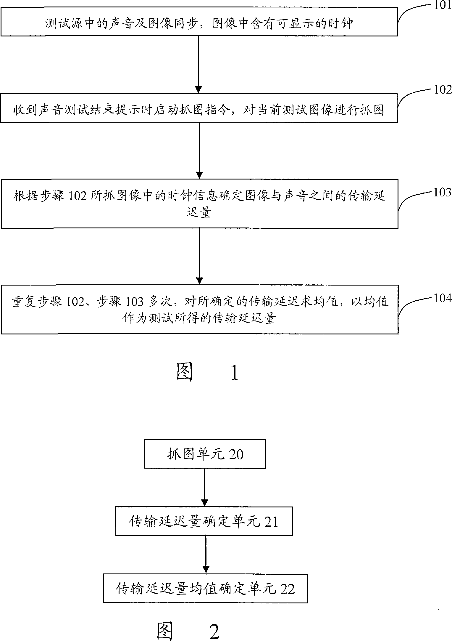
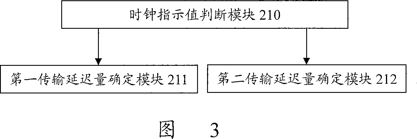
[0033] The core idea of ​​the present invention is: the existing labial sound test method is too much influenced by human factors, the test results are very different and there is no quantification standard, which is very unfavorable for the labial sound synchronization debugging of the system. In response to this problem, the present invention inserts a displayable clock into the image of the lip sound test source, and sets the clock cycle period to be equal to the duration of the cycle signal in the standard signal source, and starts to capture the image when receiving the sound prompt of the end of the test The instruction captures the current test image. Since the captured image includes clock information, the transmission delay between the image and the sound can be determined by comparing the clock information in the current image with the clock cycle. The lip sound test result of the present invention is quite accurate, which will be very beneficial to the synchronous de...


PUM


Abstract

The invention discloses a testing method for lip synchronization, which relates to the testing technology of lip synchronization, and is proposed to solve the inaccurate testing results of the current lip synchronization. clock, the method comprises the following steps: A. start the capture command when receiving the sound test end prompt, and capture the current test image; B. determine the transmission delay between the image and the sound according to the clock information in the captured image quantity. The present invention also discloses a device for realizing the above method at the same time. The test result is quite accurate by using the method and the device of the present invention, which is very beneficial to the synchronous debugging of the system for labial sounds.

Description

technical field [0001] The invention relates to lip synchronization technology, in particular to a testing method and device for lip synchronization. Background technique [0002] At present, multimedia technology has been greatly developed, and VCD, DVD, video conferencing, online games, etc. all involve multimedia technology. Audio and image signals are integrated in multimedia data, and there is a strict synchronization relationship between them. However, due to the different encoding techniques of audio and image signals, they generally need to be transmitted separately, and synchronization technology is used to keep them synchronized during transmission. The transmission process is briefly described as follows: [0003] As audio and video packets leave the sender, audio packets are paired with corresponding video packets. However, various queuing algorithms treat audio packets differently than video packets when passing through an IP router. This will disrupt the co...

Claims


Application Information

Patent Timeline
IPC IPC(8): H04N7/60H04N7/62
Inventor 苏春梅
Owner ZTE CORP
Learn More