
Special incinerator for cleaning extruder screws
An incinerator and machine screw technology, applied in the field of incinerators, can solve the problems of inconvenient ash removal, poor cleaning effect, insufficient incineration, etc., and achieve the effect of convenient ash removal, good cleaning effect and short cleaning cycle
- Summary
- Abstract
- Description
- Claims
- Application Information
AI Technical Summary
Problems solved by technology
Method used
Image

Examples
Embodiment Construction
[0009] The specific content of the present invention will be described in detail below in conjunction with the accompanying drawings and specific embodiments.
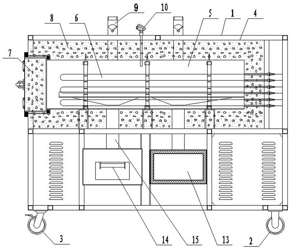
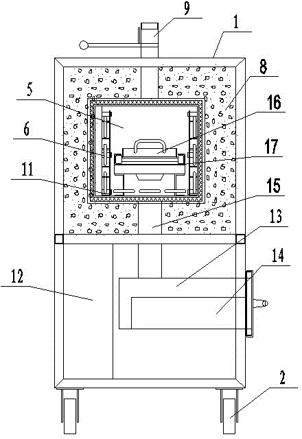
[0010] Such as figure 1 , figure 2 As shown, the special incinerator for extruder screw cleaning includes: a furnace body 1, a directional wheel 2 and a universal wheel 3 arranged at the bottom of the furnace body 1, and a shield 4 is arranged on the upper end of the furnace body 1, and a shield 4 is arranged on the upper end of the furnace body 1. A furnace 5 is arranged inside the cover 4, and a plurality of electric heating tubes 6 are evenly arranged in the furnace 5, and a sealed door 7 is arranged at one end of the furnace 5, between the furnace 5 and the shield 4 An insulating layer 8 is arranged between them, a smoke exhaust port 9 and a temperature measuring element 10 are arranged on the shield 4, an electric heating tube shelf 11, a drawer-type charging tray 16 and a drawer-type Guide rail 17, a control c...
PUM
 Abstract
Description
Claims
Application Information