Method for shearing LED pins of plug-in LED light bar plate

A technology of LED light strips and pins, applied in the application field of LED display, can solve the problems of inconvenient cutting and moving of LED pins, low cutting efficiency, and high cost of cutting machines, and achieves convenient storage box and one-handed Operation control button, saving manual operation time, simple structure effect

Active Publication Date: 2015-03-25
厦门沃为智能科技有限公司
View PDF6 Cites 0 Cited by
  • Summary
  • Abstract
  • Description
  • Claims
  • Application Information

AI Technical Summary

Problems solved by technology

[0007] The technical problem to be solved by the present invention is to provide a method for cutting LED pins of plug-in LED light strips, which solves the inconvenience of cutting and moving the LED pins of plug-in LED light strips in the prior art, and the cost of the cutting machine. The problem of high and low cutting efficiency

Method used


Image

  • Method for shearing LED pins of plug-in LED light bar plate

Examples


Embodiment Construction

[0029] Below in conjunction with accompanying drawing, structure and working process of the present invention will be further described.

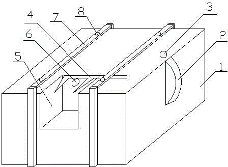
[0030] Such as figure 1 As shown, a method for cutting LED pins of plug-in LED light strips, the method is based on an LED pin cutting device for plug-in LED light strips, the device includes a controller, an in-position detection sensor 6, a storage box 1, Pin cutting groove 5, scissors 4, two moving guide rails 7 for LED light strips, pin cutting grooves 5 are set on the top edge and side edges of the storage box 1, and the scissors 4 are set In the pin cutting groove 5, the scissors of the scissors 4 face the outside of the pin cutting groove 5, and the two plug-in LED light strip moving guide rails 7 are arranged in parallel above the storage box, and are respectively located on the pins. On both sides of the cut groove 5, a pulley 8 and a control motor are installed in the moving guide rail 7 of the plug-in LED light strip. The contro...


PUM


Abstract

The invention discloses a method for shearing LED pins of a plug-in LED light bar plate. The method is based on a device for shearing LED pins of a plug-in LED light bar plate. The device comprises a controller, an in-place detection sensor, a storage box, a pin shearing groove, shearing nippers and two LED light bar plate moving guide rails. A central processor of the controller is used for driving a motor to move in the guide rails so as to drive the plug-in LED light bar plate to move, automatic shearing of the shearing nippers and automatic operation of the motor are controlled according to LED lamp pin in-place information detected through the in-place detection sensor, workers do not need to control buttons to control actions of the shearing nippers, the automation degree is enhanced, manual operation time is saved, and pin shearing work efficiency is improved.

Description

technical field [0001] The invention belongs to the application field of LED display screens, and in particular relates to a method for cutting LED pins of a plug-in LED lamp strip. Background technique [0002] The leg cutting machine is mainly used to cut off the redundant pins after soldering of components. This machine is assembled from parts manufactured by precision technology. The key parts are ground and the imported bearings are assembled and cut with good consistency. The blade rotates fast and smoothly. , low noise, high efficiency, easy operation and so on. The stroke of the double guide rails is adjusted synchronously, and the height of the cutting feet can be adjusted at will. [0003] The leg cutting machine is a special equipment for cutting and processing the remaining legs of the circuit board after dipping and soldering by using a high-speed rotating tungsten steel alloy blade. It is a special equipment for cutting and processing the remaining feet of th...

Claims


Application Information

Patent Timeline
Patent Type & Authority Applications(China)
IPC IPC(8): B21F11/00
CPCB21F11/00
Inventor 高珺胡国良朱霞
Owner 厦门沃为智能科技有限公司
Why Eureka
Try Eureka