Serial-parallel circuit for testing ageing of multiple direct-current power supplies

A DC power supply and aging test technology, applied in the field of power supply, can solve problems such as uneven current distribution between branches of voltage source parallel circuit, aging energy dispersion of low-power DC power supply, poor adaptability of products with various capacity levels, etc., so as to facilitate popularization Use, simple structure, strong practical effect

CN104678324AInactive Publication Date: 2015-06-03XIAN ZHONGKEMAITE ELECTRONICS TECH EQUIP
0 Cites 2 Cited by

Patent Information

Authority / Receiving Office
CN · China
Patent Type
Applications(China)
Current Assignee / Owner
Publication Date
2015-06-03
Estimated Expiration
Not applicable · inactive patent

Smart Images

  • Figure 1
    Figure 1
Patent Text Reader

Abstract

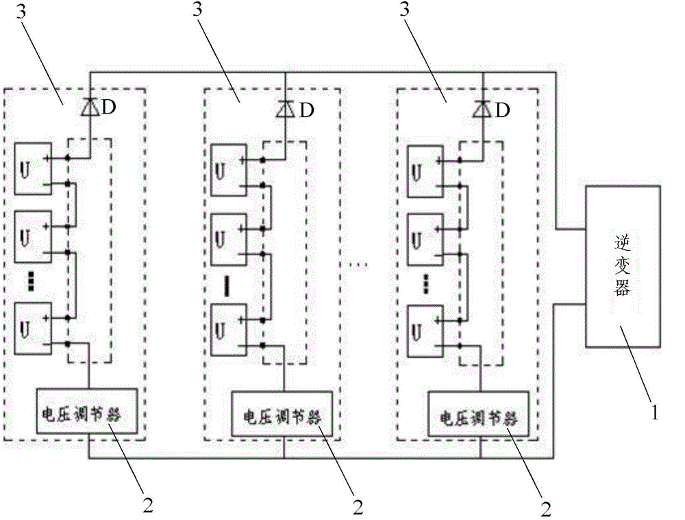
The invention discloses a serial-parallel circuit for testing ageing of multiple direct-current power supplies. The serial-parallel circuit comprises a plurality of parallel power supply rail branches and an inverter, wherein each power supply serial branch consists of a diode D for avoiding commutation between the power supply serial branches, a voltage regulator for regulating voltage of each serial branch and a plurality of serial direct-current power supplies U; series-connected positive electrodes of the direct-current power supplies U are connected with a positive electrode of a diode D; series-connected negative electrodes of the direct-current power supplies U are connected with an input end of the voltage regulator; a negative electrode of the diode D is connected with a positive electrode input end of the inverter; an output end of the voltage regulator is connected with a negative electrode input end of the inverter; an output end of the inverter is connected with a power grid. The serial-parallel circuit is simple in structure, reasonable in design, convenient in wiring, high in practicability, good in using effect and convenient to popularize and use, can realize that a plurality of small-power power supplies participate in ageing simultaneously, and realizes energy recycling during ageing test of a medium-small-power power supply.
Need to check novelty before this filing date? Find Prior Art

Description

technical field

[0001] The invention relates to the technical field of power supplies, in particular to a series-parallel circuit for aging testing of multiple DC power supplies. Background technique

[0002] As a power supply device for electronic equipment, DC power supply has been widely used in computer, communication, railway, aerospace, household appliances and other fields. In order to improve the stability and reliability of power supply products, manufacturers at home and abroad generally adopt the resistance energy consumption method to carry out aging tests on small and medium power supplies. China is the world's largest manufacturer of small and medium power power supply products. Traditional aging test methods cause huge waste of energy and poor adaptability to products of various capacity levels. Therefore, research on more economical and adaptable energy-saving aging test systems is of great importance. Very important.

[0003] However, there are still a lot...

Examples

Embodiment Construction

[0018] like figure 1 As shown, the present invention includes a plurality of power supply series branches 3 connected in parallel and an inverter 1 for sending electricity into the power grid, and each of the power supply series branches 3 is used to avoid the gap between the power supply series branches 3 The commutation diode D, the voltage regulator 2 for adjusting the voltage of each series branch circuit, and a plurality of DC power supplies U connected in series, the anodes of the plurality of DC power supplies U connected in series are connected to the anodes of the diode D, The negative poles of the plurality of DC power supplies U connected in series are connected to the input terminal of the voltage regulator 2, the negative poles of the diode D are connected to the positive pole input terminal of the inverter 1, and the voltage regulator 2 The output end of the inverter 1 is connected to the negative input end of the inverter 1, and the output end of the inverter 1 ...