Spiral type ground nail with locking function

A spiral and ground nailing technology, which is applied to sheet pile walls, building types, buildings, etc., can solve the problems of time-consuming, laborious, and unsuitable for the weak, and achieve the effect of quickly inserting into the ground

Inactive Publication Date: 2015-06-17
DEQING YICHENG IMPORT & EXPORT
View PDF7 Cites 0 Cited by
  • Summary
  • Abstract
  • Description
  • Claims
  • Application Information

AI Technical Summary

Problems solved by technology

It is often laborious and time-consuming to use this method, and it is not suitable for the weak.

Method used


Image

  • Spiral type ground nail with locking function

Examples


Embodiment Construction

[0014] Combine below figure 1 Specific description embodiment:

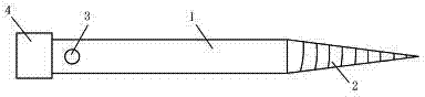
[0015] Such as figure 1 As shown, the screw-type ground nail with locking, the described screw-type ground nail with locking includes an intermediate piece 1, one end of the middle piece 1 is connected with a spiral nail head 2, and the other end of the middle piece 1 A radial through hole 3 is opened near the end at one end.

[0016] Preferably, the intermediate piece 1 is connected with a connecting piece 4 at one end close to the radial through hole 3 .

[0017] Preferably, the intermediate piece is a hollow tube.

[0018] Preferably, the ratio of the length of the intermediate piece to the screw head is 3:1-4:1.

[0019] When in use, the nail head can be directly inserted into the ground a little first, and then inserted into the radial through hole using a cross bar. Use the cross bar to rotate the ground nail so that the nail head can be continuously rotated into the ground until the whole installation...


PUM


Abstract

The invention belongs to the technical field of flagpole tools and particularly relates to a spiral type ground nail with a locking function. The spiral type ground nail with the locking function, disclosed by the invention, is characterized in that the spiral type ground nail with the locking function comprises a middle piece; one end of the middle piece is connected with a spiral type nail head; and a radial through hole is formed in the part, close to the end part, of the other end of the middle piece. The spiral type ground nail with the locking function has the beneficial effects that time and labor can be saved, and the spiral type ground nail can be very conveniently and rapidly inserted into the ground.

Description

technical field [0001] The invention belongs to the technical field of flagpole appliances, in particular to a screw-type ground nail with locking. Background technique [0002] At present, when the flagpole is used outdoors, the ground nail is generally inserted into the ground, and then the flagpole is inserted on the ground nail. The structure of the currently used ground nails more or less includes a nail head and a nail body. The nail heads are generally flat and pointed, and can be inserted into the ground with less effort when in use. When using such ground nails, it is generally necessary to use an auxiliary object such as a hammer to knock on the nail body, so that the ground nails can be inserted into the ground for fixing. It is often laborious and time-consuming to use this method, and it is not suitable for the weak. Contents of the invention [0003] The purpose of the present invention is to solve the above-mentioned technical problems, to provide a screw-...

Claims


Application Information

Patent Timeline
Patent Type & Authority Applications(China)
IPC IPC(8): E02D5/80E04H12/22
CPCE04H12/2215
Inventor 阎学议
Owner DEQING YICHENG IMPORT & EXPORT
Why Eureka
Try Eureka