
An assembled pipe jacking pit support structure and its construction technology

A supporting structure and working pit technology, which is applied in the direction of basic structure engineering, underwater structures, artificial islands, etc., can solve problems such as not being suitable for small-scale construction, not having the function of water retaining, and requiring drilling equipment, etc., to achieve The effect of saving installation time, shortening construction period, shortening project period and cost

Active Publication Date: 2021-06-29
北京诺和兴建设工程有限公司
View PDF6 Cites 0 Cited by
  • Summary
  • Abstract
  • Description
  • Claims
  • Application Information

AI Technical Summary

Problems solved by technology

However, this construction method has high construction cost and complicated process, and due to the influence of concrete curing period, the construction period is long. The caisson method is more commonly used when the geological conditions are poor, there is surface water or the groundwater level is high.
3) Cast-in-situ piles; cast-in-place piles have the advantages of high rigidity and flexible layout, but they need to be used as horizontal cover beams and waist beams and do not have the function of retaining water. In addition, auxiliary anti-seepage measures are required, and drilling equipment and mud retaining walls are required , high economic cost, not suitable for small-scale construction
[0004] When the pipe jacking construction is carried out in the rainy season, the construction is difficult, and it is necessary to quickly complete the support of the working pit to ensure the normal and rapid progress of the pipe jacking. The above four supporting methods of the working pit not only have a long construction period, but also support The construction cost of protection is also high, it is difficult to meet the requirements

Method used


Image

  • An assembled pipe jacking pit support structure and its construction technology
  • An assembled pipe jacking pit support structure and its construction technology
  • An assembled pipe jacking pit support structure and its construction technology

Examples


Embodiment Construction

[0043] The present invention will be described in further detail below in conjunction with the accompanying drawings.

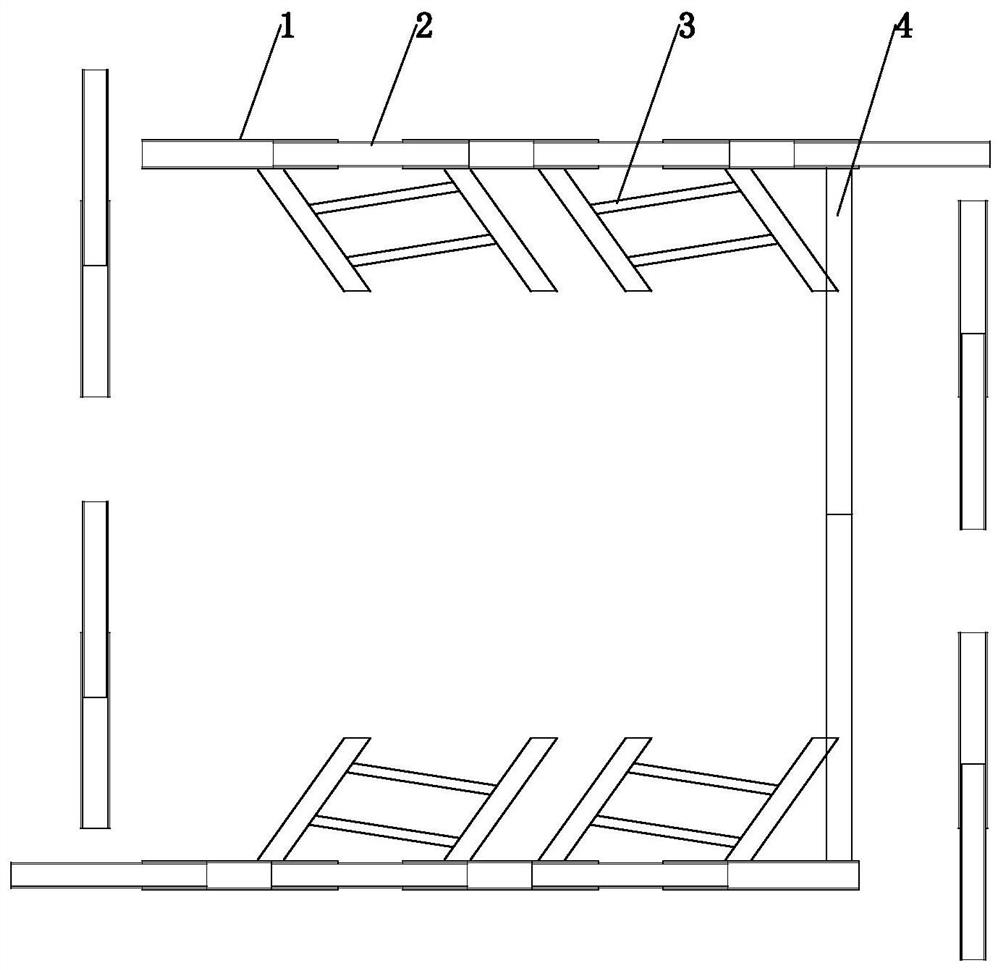
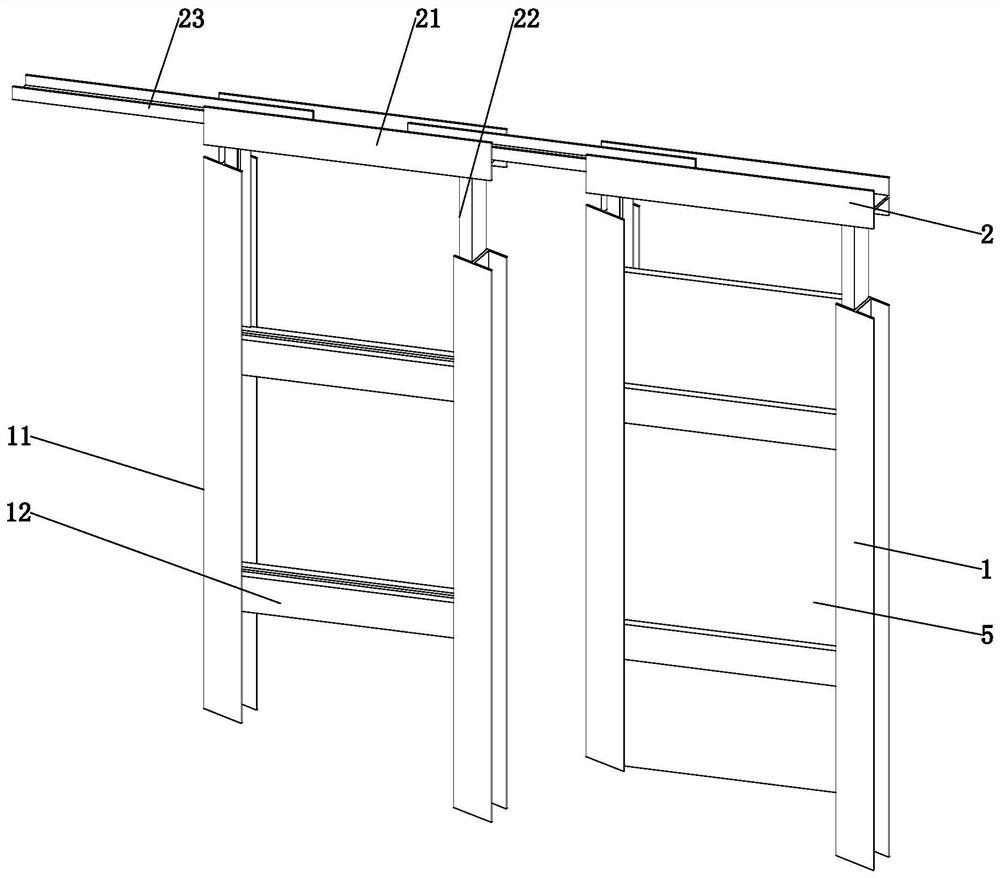
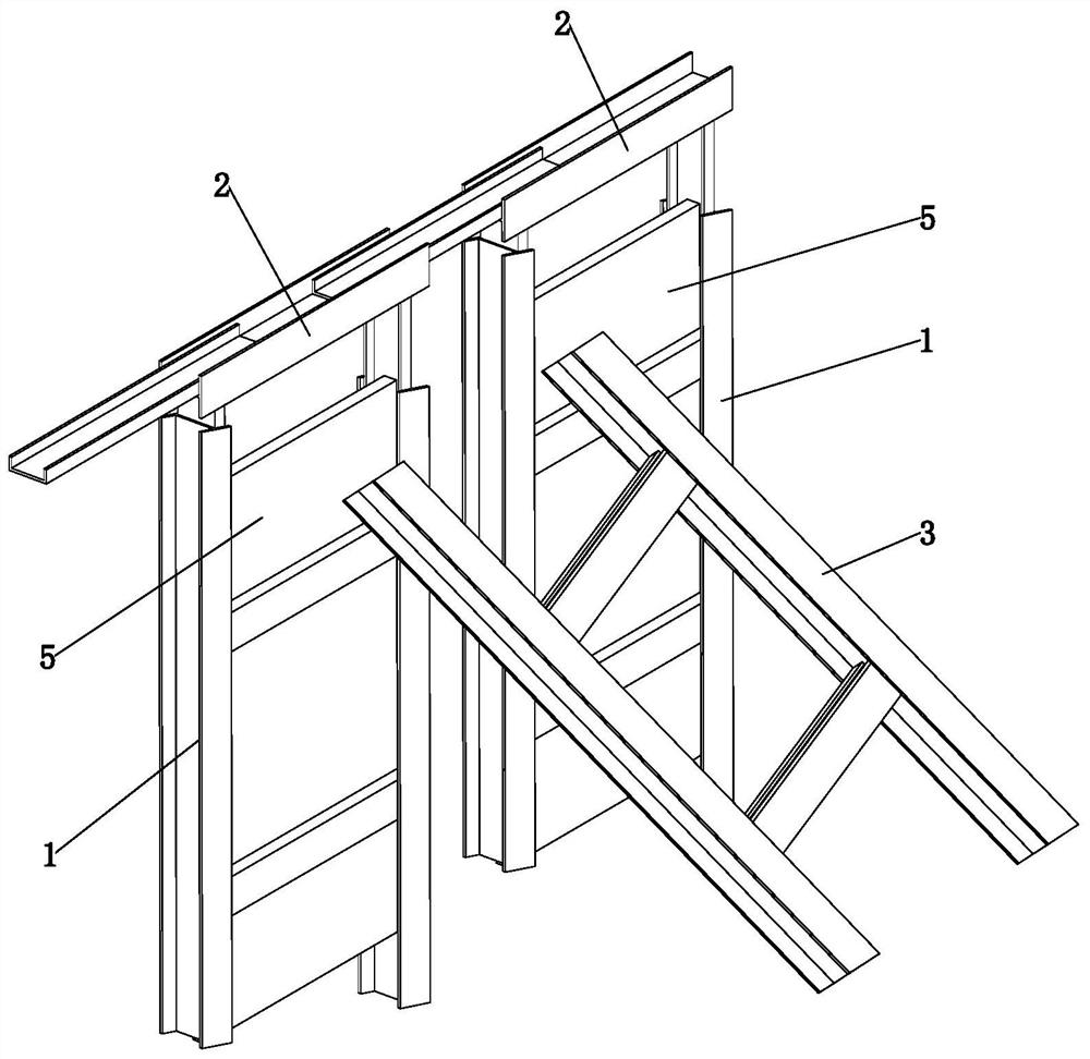
[0044] refer to figure 1 , is an assembled pipe jacking work pit support structure disclosed by the present invention, including a pit wall support structure and a support reinforcement structure, arranged in the work pit, and the work pit is set as a rectangular pit.

[0045] Among them, the pit wall support structure includes a support frame 1 and a connecting frame 2, several support frames 1 are arranged along the inner wall of the working pit, and one-third of the support frames 1 are kept between adjacent support frames 1. Width distance, the upper end of each supporting frame 1 is connected with a connecting frame 2, the lower end of the supporting frame 1 is buried in the soil layer at the bottom of the working pit, two adjacent connecting frames are connected together, and the supporting frame 1 Connect with the connecting frame 2 on the inner wall ...


PUM


Abstract

The invention relates to an assembled pipe jacking working pit support structure, comprising a pit wall support structure and a support reinforcement structure; the pit wall support structure includes a plurality of support frames arranged along the inner wall of the work pit and a The connecting frame on the top of the support frame, the lower end of the support frame is buried in the bottom of the work pit, the upper end is connected with the connecting frame, and the adjacent connecting frames are connected together; the support and strengthening structure includes a lower support frame and an upper part The support frame, the lower support frame has the same structure as the support frame, and is connected between the support frame and the bottom of the working pit, and the upper support frame has the same structure as the support frame and is connected between the two opposite support frames. between. The invention adopts a prefabricated support structure, which can quickly support in the working pit, has fast installation speed and high support strength.

Description

technical field [0001] The invention relates to the technical field of engineering construction, in particular to an assembled pipe jacking pit support structure and a construction process thereof. Background technique [0002] Pipe jacking construction, as the earliest trenchless construction technology, has been widely used in the construction of municipal drainage pipes due to its advantages of short construction period, high precision, high degree of construction civilization, and little interference to traffic. With the popularization of this technology, there are more and more application occasions, especially in the surrounding buildings, not only the walls of the working pit are required to be stable, but also the safety of buildings, roads, pipelines, etc. around the foundation pit must be ensured. , thus putting forward higher requirements for the support of the pipe jacking pit. [0003] At present, the commonly used support methods for working pits include the f...

Claims


Application Information

Patent Timeline
Patent Type & Authority Patents(China)
IPC IPC(8): E02D17/08E02D29/12
CPCE02D17/08E02D17/083E02D29/12
Inventor 刘红印张玉侠杨金辉张子硕
Owner 北京诺和兴建设工程有限公司
Learn More