AI technical title is built by PatSnap AI team. It summarizes the technical point description of the patent document.
A robot, direct-drive technology, applied in conveyor objects, manipulators, transportation and packaging, etc., can solve the problems of different shafts of transmission shafts, eccentric transmission loads, installation difficulties, etc., achieve high transmission accuracy, reduce intermediate links, Electrically controlled simple effects
What is AI technical title?
AI technical title is built by PatSnap AI team. It summarizes the technical point description of the patent document.
A robot, direct-drive technology, applied in conveyor objects, manipulators, transportation and packaging, etc., can solve the problems of different shafts of transmission shafts, eccentric transmission loads, installation difficulties, etc., achieve high transmission accuracy, reduce intermediate links, Electrically controlled simple effects
CN104723332BActive 📅 Publication Date: 2017-04-05BEIJING UNIV OF TECH
Click on the blue label to locate the original text in one second.
Reading with bidirectional positioning of images and text.
Examples
Embodiment Construction
[0039] Specific embodiments of the present invention will be described in detail below in conjunction with specific drawings.
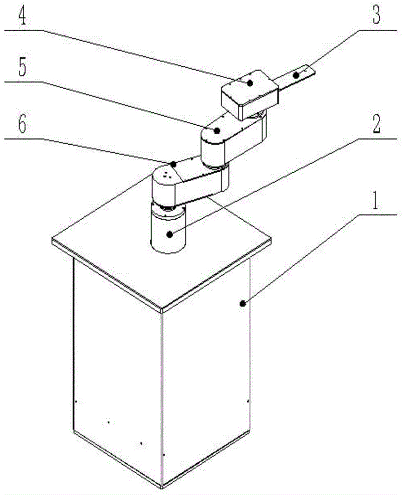
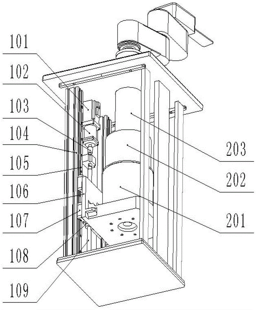
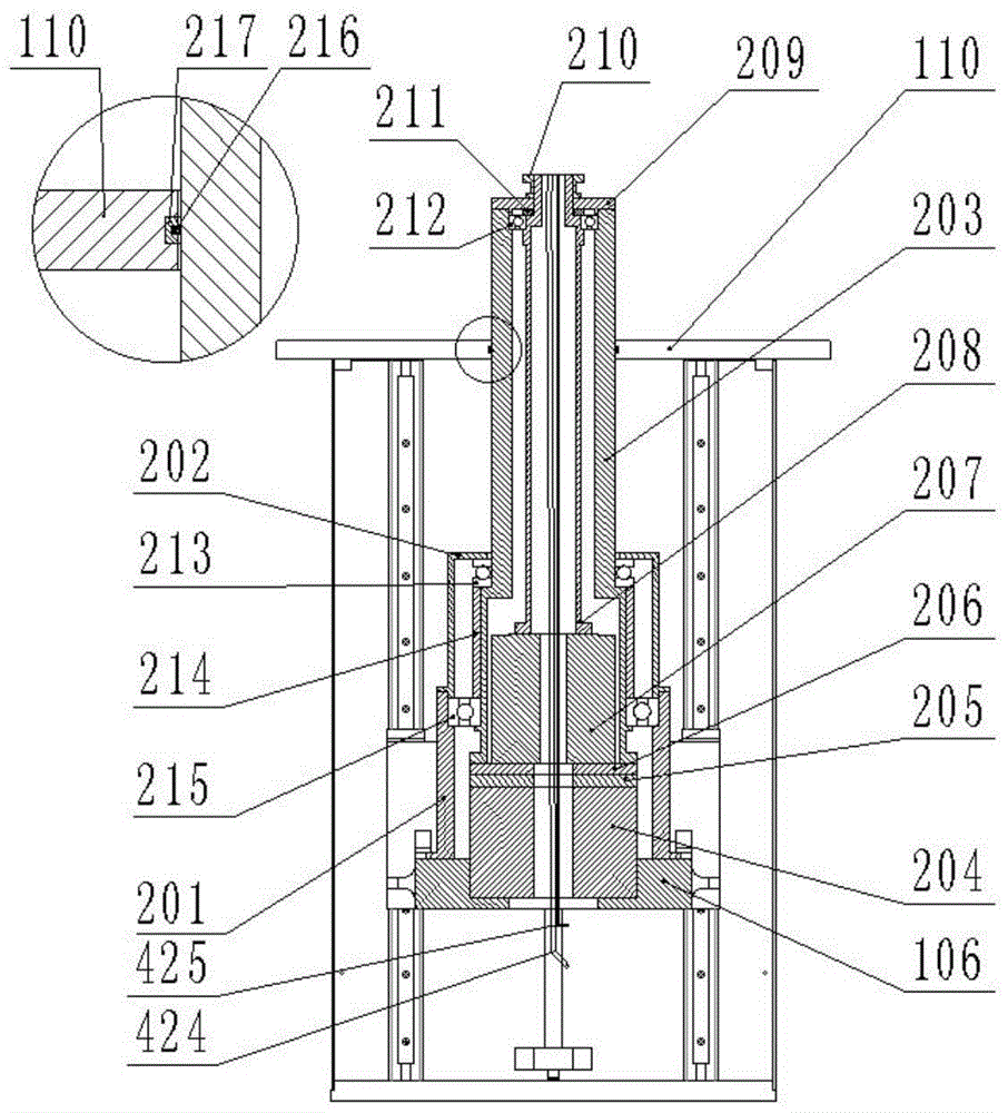
[0040] Such as Figure 1-6 As shown, a direct-drive reversible wafer transfer robot includes a base 1, a lifting and rotating mechanism 2, a vacuum suction end 3, a turning wrist 4, a small arm 5 and a large arm 6; the base 1 Lifting and slewing mechanism 2 is installed inside, and lifting and slewing mechanism 2 is connected with boom 6 one end (near end), and boom 6 other end (far end) is connected with forearm 5 one end (near end), and forearm 5 other end (near end) The far end) is connected with one end of the turning wrist 4, and the other end of the turning wrist 4 is connected with the vacuum suction end 3.
[0041] When the wafer transfer robot moves, the base 1 is fixed, and the lifting and rotating mechanism 2 can rotate around the center of the base 1, and can also perform lifting motion along the vertical direction (Z direction) of the ba...
PUM
Abstract
The invention discloses a direct drive type reversible wafer transmission robot. A lifting and dropping and swing mechanism is installed on the inner portion of a base seat, the lifting and dropping and swing mechanism is connected with one end of a big arm, the other end of the big arm is connected with one end of a small arm, the other end of the small arm is connected with one end of a reverse wrist, and the other end of the reverse wrist is connected with a vacuum adsorption tail end. When the wafer transmission robot moves, a three-connection rod which composed of the big arm, the small arm and the reverse wrist fixes a specific speed movement, and a straight line expansion movement in the radial direction is achieved; a motor is used for driving the vacuum adsorption tail end, so that a reverse movement of the reverse wrist is achieved; by the adoption of the direct drive motor to drive directly, an interior structure of the robot is simplified, the number of intermediate links is reduced, and the rotating precision and the rotating efficiency of the robot are improved. Due to fewer part mechanisms, the robot is convenient to assemble and produce. A steel belt is used rotatably, so that the rotating precision is provided, the reliability of the robot is enhanced, the production of contaminant particles is lowered, and the level of cleanliness of the robot is improved. The degree of freedom of reversing of the robot is increased by the reverse wrist, and the range of application of the robot is enlarged.
Description
technical field [0001] The invention relates to the field of automatic wafer handling equipment, in particular to a wafer transfer cleaning robot. Background technique [0002] In the VLSI manufacturing process, wafers need to be frequently transferred between hundreds of processes. The wafer production line has concentrated processes, fast processing speed, and high requirements for cleanliness in the working environment. High-performance wafer transfer robots are required. . The existing R-θ type wafer transfer robot is mostly driven by a servo motor (stepping motor) coupled with a reducer to decelerate and then drive the transmission shaft to rotate. The transmission structure is complex and difficult to install, and most reduction mechanisms (belt transmission, gear transmission etc.) will bias the transmission shaft, which is more likely to cause unbalanced load and redundant radial force, resulting in loss of motor torque and reduced accuracy. Driven by a direct-driv...
Claims