AI technical title is built by Patsnap AI team. It summarizes the technical point description of the patent document.
A technology for connecting splints and splint sections, which is applied in the connection of rods, connecting components, and scaffolding, etc., can solve the problems of complex structure and difficult construction of connecting nodes of quick-installation racks, and achieves simple and easy operation and production. , The effect of eliminating the installation and dismantling process
Active Publication Date: 2017-07-07
朱宏宇
View PDF12 Cites 0 Cited by
Summary
Abstract
Description
Claims
Application Information
AI Technical Summary
This helps you quickly interpret patents by identifying the three key elements:
Problems solved by technology
Method used
Benefits of technology
Problems solved by technology
[0013] The purpose of the present invention is to provide a forward inclined multi-directional three-dimensional connection splint joint, quick-loading frame and its application, to solve the technical problems of complex connection node structure and difficult construction of the traditional fast-loading frame; Increase the flexibility of connection installation and the issue of safety and stability
Method used
Image
Click on the blue label to locate the original text in one second.
Reading with bidirectional positioning of images and text.
Examples
Embodiment Construction
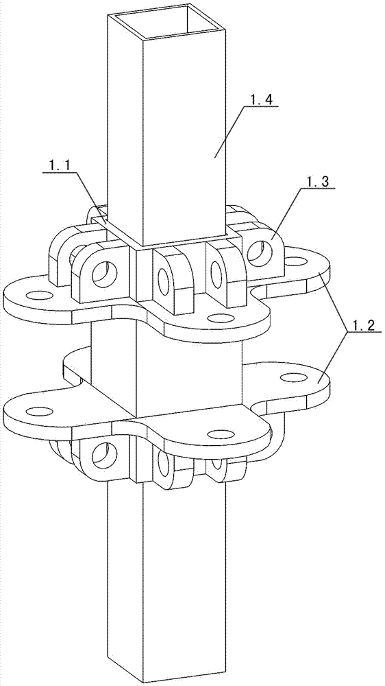
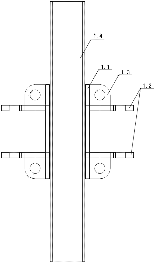
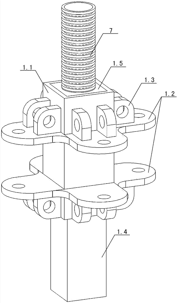
[0073] Examples see figure 1 , figure 2 As shown, this forward-oblique multi-directional three-dimensional connection splint section includes a joint core 1.1 and a splint. The splint section is an independent connector that can realize forward and oblique multi-directional connections. , snap ring 1.3 and joint pin 1.4 are integrally cast; see figure 1 , figure 2 As shown, a knot pin 1.4 is fixed inside the joint core 1.1, and the joint pin 5 is a square tube or a round tube, and at least one end exceeds the joint core to form a vertically connected joint pin.
[0074] see Figure 5 , Image 6 As shown, the joint core 1 is a vertical pipe section with a vertical through hole; there is at least one clamping plate 1.2 on at least two vertical sides of the joint core outer wall; the clamping plate 1.2 is composed of a pair of mutually parallel and spaced plates Tongues, each pair of plate tongues are respectively provided with at least one connecting hole; forming horizon...
PUM
Abstract
The invention discloses a positively-biased multidirectional three-dimensional connected clamp plate link, a quick-release frame, an application and a method of the positively-biased multidirectional three-dimensional connected clamp plate link and the quick-release frame. The clamp plate link comprises a knob core, a clamp plate, a clamp ring and a knob pin, and is an independent connecting piece capable of simultaneously realizing forwardly, obliquely and multidirectional connecting or concentrically connecting in a same point way; the quick-release frame is a planar frame or a three-dimensional frame formed by mutually assembling an upright bar, a flat bar and an oblique bar; the clamp plate link and the quick-release frame can be applied to a carrying frame, a bailey frame, a bridge frame, a storage rack, a frame, a crane carriage, an elevator frame, a suspension frame, a lifting frame and a carrying frame to be quickly dismounted, especially a scaffold, a template support and the like in the engineering construction field; the independent nodes and independent rod pieces of the quick-release frame can be realized in a solderless manufacturing and pin fixed connection way, the same-point, same-node, coplanar and concentric connection can be realized, the multi-directional bearing, flexibility and diversity and variation can be realized; in addition, the clamp plate link is safe and convenient, firm and durable, accurate and quick.
Description
technical field [0001] The invention relates to a connecting piece, a quick-loading rack using the connecting piece, an application and a method thereof. Background technique [0002] In the fields of engineering construction, warehousing, and shipbuilding, a large number of quick-installation racks that need to be installed quickly and can be quickly disassembled are required, such as quick-installation scaffolding, operating racks, shelves, bridges, etc. [0003] As we all know, the general quick-loading rack is a frame structure formed by combining and connecting rods; the stable quick-loading rack rods are generally composed of vertical rods, flat rods, and oblique rods, and the rods are connected or welded with connectors. Form a quick release rack. The rods that make up the quick release rack are common objects, such as steel pipes, etc. The core problem in preparing the quick release rack is the connection. Most of the connection designs of traditional quick-release...
Claims
Application Information
Patent Timeline
Application Date:The date an application was filed.
Publication Date:The date a patent or application was officially published.
First Publication Date:The earliest publication date of a patent with the same application number.
Issue Date:Publication date of the patent grant document.
PCT Entry Date:The Entry date of PCT National Phase.
Estimated Expiry Date:The statutory expiry date of a patent right according to the Patent Law, and it is the longest term of protection that the patent right can achieve without the termination of the patent right due to other reasons(Term extension factor has been taken into account ).
Invalid Date:Actual expiry date is based on effective date or publication date of legal transaction data of invalid patent.

