
Tail gas treatment device suitable for automobile exhaust pipe

A technology for tail gas treatment and automobile exhaust, which is applied in the direction of exhaust devices, noise reduction devices, engine components, etc., and can solve the problems of affecting the service life of automobile exhaust pipe exhaust treatment devices, damage to the body of exhaust gas treatment devices, and high load of automobile exhaust pipes, etc. Problems, to achieve good vibration reduction protection effect, reduce damage, improve the effect of service life

Inactive Publication Date: 2020-09-01
合肥鑫逸昂自动化设备有限公司
View PDF8 Cites 0 Cited by
  • Summary
  • Abstract
  • Description
  • Claims
  • Application Information

AI Technical Summary

Problems solved by technology

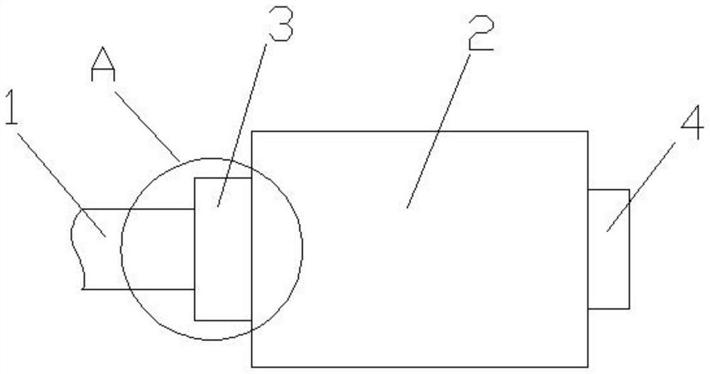
However, the existing exhaust gas treatment device has a large volume and weight, and the load on the exhaust pipe of the automobile is relatively high. figure 1 as shown, figure 1 It is a schematic diagram of the connection between the exhaust gas treatment device and the exhaust pipe of the car in the prior art. When the car is running at high speed or / and bumps, the sway and vibration of the car body will cause damage to A and the body of the exhaust gas treatment device, which will affect the car body. The service life of the exhaust pipe and the exhaust gas treatment device, therefore, considering the cost of accessories, the exhaust gas treatment device needs to be improved

Method used


Image

  • Tail gas treatment device suitable for automobile exhaust pipe
  • Tail gas treatment device suitable for automobile exhaust pipe
  • Tail gas treatment device suitable for automobile exhaust pipe

Examples


Embodiment Construction

[0018] In order to make the purpose, technical solutions and advantages of the embodiments of the present invention more clear, the technical solutions in the embodiments of the present invention will be clearly and completely described below in conjunction with the drawings in the embodiments of the present invention.

[0019] In the description of the present invention, it should be noted that unless otherwise specified, the meaning of "plurality" is two or more; the terms "upper", "lower", "left", "right", "inner ", "outside", "front end", "rear end", "top", "bottom" and other indicated orientations or positional relationships are based on the orientations or positional relationships shown in the drawings, and are only for the convenience of describing the present invention and simplifying the Describes, but does not indicate or imply that the device or element referred to must have a specific orientation, be constructed in a specific orientation, and operate in a specific o...


PUM


Abstract

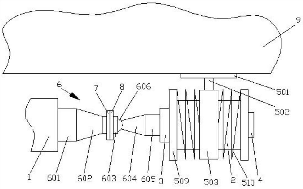
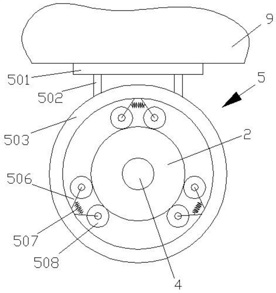
The invention discloses a tail gas treatment device suitable for an automobile exhaust pipe, and relates to the technical field of automobile accessories. The device comprises a body, a gas inlet pipearranged on one side of the body and a gas outlet pipe arranged on the other side of the body; a venturi tube is connected between an exhaust pipe and the gas inlet pipe, and the venturi tube comprises a cylindrical throat part, and a hollow spherical joint is clamped in cylindrical throat part in a matched manner; a buffering device is arranged on the body, the buffering device comprises a connecting plate fixedly connected with the bottom of an automobile, a connecting rod is arranged at the bottom of the connecting plate, a lantern ring is connected to the bottom end of the connecting rod,an annular groove is formed in the inner wall of the lantern ring, and multiple sidling wheel groups connected with the exterior of the body in an abutting mode are arranged in the annular groove; and protruding rings are arranged on the side portions of the two sides of the body, second springs are connected between the protruding rings and the side portions of the lantern rings, and the body issleeved with the second springs. According to the device, the tail gas treatment device can be well stabilized on the exhaust pipe, the damage to the automobile exhaust pipe can be reduced, and meanwhile, the good vibration reduction protection effect on the device body is achieved.

Description

technical field [0001] The invention relates to the technical field of automobile accessories, in particular to an exhaust gas treatment device suitable for automobile exhaust pipes. Background technique [0002] After the combustion of automobile gasoline, a large amount of harmful gases are produced, mainly including carbon monoxide, hydrocarbons, and nitrogen oxides. Generally, a three-way catalytic converter is installed in the middle of the exhaust pipe to process the above-mentioned mixed harmful gases to generate carbon dioxide. and water before being released into the atmosphere. Nevertheless, after the original exhaust gas passes through the three-way catalytic converter, it still contains more particulate impurities, heat and unremoved harmful gases. Therefore, in order to reduce the harm caused by automobile exhaust to the environment, it is used to further purify automobile exhaust. Processing devices have emerged as the times require, and this kind of auto part...

Claims


Application Information

Patent Timeline
Patent Type & Authority Applications(China)
IPC IPC(8): F01N13/08F01N13/18
CPCF01N13/08F01N13/18F01N13/1855
Inventor 汪家贵张国春陈胜
Owner 合肥鑫逸昂自动化设备有限公司
Learn More