A low-voltage power distribution AC cabinet

A low-voltage power distribution and cabinet technology, which is applied to the substation/distribution device shell, and the cooling/ventilation of substation/switchgear. Easy to disassemble, reduce the overall weight, and save labor costs

Inactive Publication Date: 2017-07-28
JIANGSU JIANGCHENG ELECTRIC
View PDF5 Cites 0 Cited by
  • Summary
  • Abstract
  • Description
  • Claims
  • Application Information

AI Technical Summary

Problems solved by technology

The electrical components and lines in the existing power distribution cabinet are in good contact and reliable connection, but because the electrical components will generate a lot of heat when they work, and the heat dissipation effect of the power distribution cabinet is not ideal, the connection ends of some electrical components and lines The head is more prone to local heating, resulting in excessive local temperature, and even heating and burning, which ultimately affects the normal use of the entire power distribution cabinet
[0003] At present, the heat dissipation of the power distribution cabinet is mainly formed by directly embossing the cabinet body to form a louver-shaped heat dissipation window. There will be a space between each embossing. The exhausted hot air bounces back into the cabinet, thus weakening the working efficiency of the exhaust fan and reducing the overall heat dissipation performance of the outdoor equipment box
In addition, the heat dissipation air duct of the power distribution cabinet is unreasonable, the ventilation hole is too small, the heat dissipation area is small, the ambient temperature inside the cabinet rises rapidly, and the operation of the equipment is unstable, which may easily cause short circuits and damage to related electronic components or parts
[0004] At the same time, during use, some blades are easy to corrode and wear. In the past, the entire cabinet was generally replaced. The cost is high, the transportation and installation are very inconvenient, and the project period is long, which directly affects the quality of production and life.

Method used


Image

  • A low-voltage power distribution AC cabinet
  • A low-voltage power distribution AC cabinet
  • A low-voltage power distribution AC cabinet

Examples


Embodiment Construction

[0022] The present invention will be further described below in conjunction with the accompanying drawings.

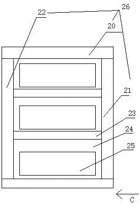
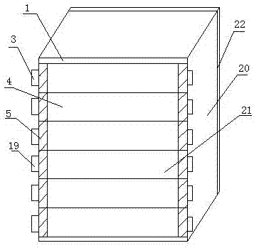
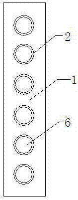
[0023] As shown in the figure, a low-voltage power distribution AC cabinet includes a cabinet body 26, which is divided into several chambers 24 by partitions 23, and electronic components 25 are placed in each chamber 24, and the cabinet body 26 includes cabinets. The body frame 20 is provided with a cabinet door 22 and a heat dissipation door 21 opposite to the cabinet body frame 20. The heat dissipation door 21 includes a door body 1, a shaft sleeve 2, a blade shaft 3, a blade 4 and a fixed casing 5. The door The body 1 is a rectangular frame structure, and the two sides of the door body 1 are evenly provided with 6 fixing holes 6, and the bushing 2 is fixed inside the fixing holes 6; the blade 4 includes a first blade 7 and the second blade 8, the first blade 7 and the second blade 8 are rectangular profiles bent outwards from the center, the cross-sectional shape ...


PUM


Abstract

The invention relates to a cabinet body of a low-voltage power distribution AC cabinet, which includes a cabinet body, which is divided into several chambers by partition boards, and electronic components are placed in each chamber. The cabinet body includes a cabinet frame, and the cabinet frame is opposite to The cabinet door and heat dissipation door are provided. The heat dissipation door includes a door body, a shaft sleeve, a blade shaft, a blade and a fixed casing. The blade includes a first blade and a second blade, and the first blade and the second blade are relatively attached. The blades are fixed together by bolts to form a whole blade. The blade rotating shaft passes through the bushing on one side of the door body, the blade and the bushing on the other side of the door body in turn, and is fixed on the door body by a rotating wheel. It is easy to install and disassemble, reduces the self-weight of the blade, greatly facilitates the construction personnel, has strong flexibility and adaptability, greatly improves the construction progress, and saves costs.

Description

technical field [0001] The invention relates to a power distribution AC cabinet, in particular to a low-voltage power distribution AC cabinet. Background technique [0002] In the power system, the power distribution cabinet is an important control and protection device, and the contact characteristics of the conductive connections in the power distribution cabinet will directly affect the reliability of the power distribution cabinet. The electrical components and lines in the existing power distribution cabinet are in good contact and reliable connection, but because the electrical components will generate a lot of heat when they work, and the heat dissipation effect of the power distribution cabinet is not ideal, the connection ends of some electrical components and lines The head is relatively easy to generate heat locally, causing the local temperature to be too high, and even generate heat and burnout, which ultimately affects the normal use of the entire power distrib...

Claims


Application Information

Patent Timeline
Patent Type & Authority Patents(China)
IPC IPC(8): H02B1/26H02B1/56
Inventor 解良洪
Owner JIANGSU JIANGCHENG ELECTRIC
Why Eureka
Try Eureka