Check patentability & draft patents in minutes with Patsnap Eureka AI!

fuel supply device

A technology of a fuel supply device and a fuel pump, which is applied in the directions of liquid fuel feeders, charging systems, engine components, etc.

Active Publication Date: 2017-07-04
HONDA MOTOR CO LTD
View PDF1 Cites 0 Cited by
  • Summary
  • Abstract
  • Description
  • Claims
  • Application Information

AI Technical Summary

Problems solved by technology

Therefore, it is necessary to add a complicated control system including an expensive pressure sensor, which may be disadvantageous in terms of cost.

Method used


Image

  • fuel supply device
  • fuel supply device
  • fuel supply device

Examples


Embodiment Construction

[0034] Hereinafter, one embodiment of the present invention will be described with reference to the drawings.

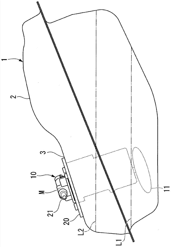
[0035] Such as figure 1 As shown, the fuel supply device 10 of the present embodiment includes a so-called top-mounted fuel pump unit M. As shown in FIG. The fuel pump assembly M is inserted into the fuel tank 1 from the opening 3 formed on the upper wall 2 of the fuel tank 1 , and is immersed in the fuel tank 1 in a state of being attached to the upper wall 2 of the fuel tank 1 and suspended. in the fuel. In the fuel tank 1, the detection of clogging of the fuel filter 11 and the detection of the first position L1 of the presence or absence of remaining fuel (gasoline shortage, fuel meter E point) and the level of the liquid level (level) are set. Start position L2.

[0036] Such as figure 2 As shown, the fuel pump assembly M includes a fuel pump 12 , a holder portion 13 , a vapor exhaust pipe 14 , and a fuel filter 11 .

[0037] The fuel pump 12 is formed in ...


PUM


Abstract

The invention project provides a fuel supply device capable of cheaply and simply detecting blocking of a fuel filter without using a high price pressure sensor; the fuel supply device comprises a fuel pump (12); the fuel filter (11); a discharge hole (22) discharging air bubbles of the fuel pump (2); a steam discharge pipe (14) with one end connected with the air discharge hole (22) and the other end configured in a gas phase position at least in a temporally time in a fuel box burning amount changing process. The fuel filter (11) is hollow, and an inner side is connected with an air inlet (17) of the fuel pump (12); along with pressure rise, a first form (A1) in the beginning can change into a second form, wherein the second form is condensed when being compared with the first form (A1); in the second form, the fuel pump can suck the gas phase through the steam discharge pipe (14) so as to elastically return to the first form (A1); form changes of the fuel filter (11) enables fuel pressure to pulse.

Description

technical field [0001] The present invention relates to a fuel supply device used in vehicles such as motorcycles (motorcycles), for example. Background technique [0002] Conventionally, there has been proposed a fuel supply device that determines the clogged lifetime based on the engine speed and the discharge amount of the fuel booster pump (see Patent Document 1). The fuel supply device disclosed in Patent Document 1 does not perform determination of the clogged life when the engine speed is equal to or lower than the first engine speed. On the other hand, when the engine speed is higher than the first engine speed, the clogged life determination threshold is calculated based on the engine speed and the discharge amount of the fuel booster pump to determine the clogged life. [0003] However, the fuel supply device disclosed in Patent Document 1 includes a pressure sensor that detects the discharge amount of the fuel booster pump. Therefore, it is necessary to add a co...

Claims


Application Information

Patent Timeline
Patent Type & Authority Patents(China)
IPC IPC(8): F02M37/22F02D45/00
Inventor 小室胜纪赤松俊二加藤裕一
Owner HONDA MOTOR CO LTD
Features
  • R&D
  • Intellectual Property
  • Life Sciences
  • Materials
  • Tech Scout
  • Unparalleled Data Quality
  • Higher Quality Content
  • 60% Fewer Hallucinations
Learn More