Supercharge Your Innovation With Domain-Expert AI Agents!

fuel supply device

A fuel supply device and fuel technology, which are applied in the directions of liquid fuel feeders, charging systems, machines/engines, etc., can solve the problems of increased mold cost and complexity of forming filter devices.

Active Publication Date: 2018-09-14
HITACHI ASTEMO LTD
View PDF2 Cites 0 Cited by
  • Summary
  • Abstract
  • Description
  • Claims
  • Application Information

AI Technical Summary

Problems solved by technology

[0009] However, since the filter device is formed in a complicated shape by combining a plurality of filters, the cost of the mold for forming the filter device increases when the design is changed.

Method used


Image

  • fuel supply device
  • fuel supply device
  • fuel supply device

Examples


Embodiment Construction

[0028] Embodiments of the present invention will be described below with reference to the drawings.

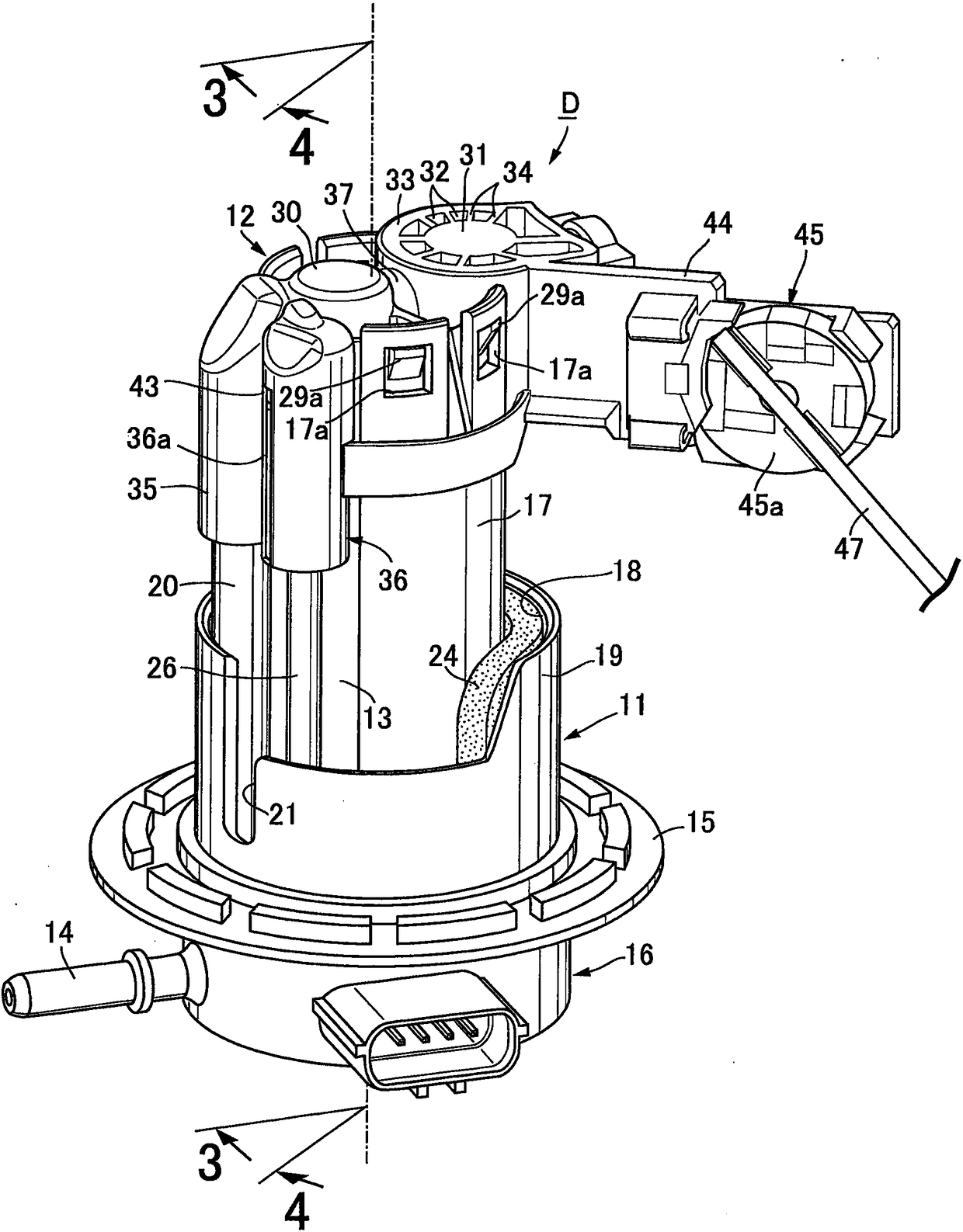
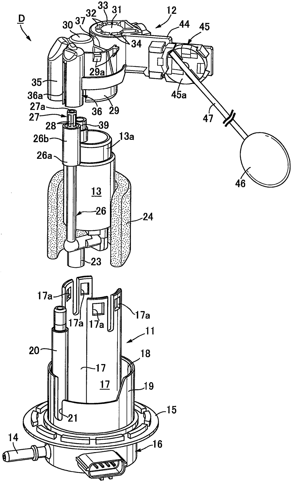
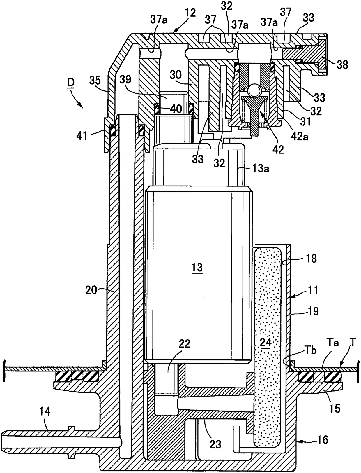
[0029] First, in Figure 1 ~ Figure 4 In this case, on the floor Ta of the fuel tank T mounted on the vehicle (refer to image 3 and Figure 4 ) is mounted with the fuel supply device D of this embodiment for supplying the fuel in the fuel tank T to a fuel injection valve (not shown) of the engine.

[0030] This fuel supply device D has: a first casing 11 made of synthetic resin attached to the bottom plate Ta of the fuel tank T; body 12; and a fuel pump 13 held between the first housing 11 and the second housing 12.

[0031]The first casing 11 is integrally formed with a bottomed cylindrical base portion 16 having a fuel take-out pipe 14 at the lower portion and an attachment flange 15 attached around the opening Tb of the bottom plate Ta of the fuel tank T at the upper portion. The base portion 16 closes the opening Tb; a pair of pump holding walls 17 having an arcuate c...


PUM


Abstract

The present invention provides a fuel supply device capable of adjusting the maximum liquid level of fuel sucked into a fuel pump from a vapor discharge passage when a suction filter is clogged without changing the design of a filter device. The upper part of the steam discharge passage is provided with a surrounding wall that surrounds the periphery of the filter device when viewed from above, and an opening is formed on the upper end or side of the surrounding wall, and the opening is opened at a position higher than the lower end of the filter so that the inside of the surrounding wall The space communicates with the internal space of the fuel tank, so when the fuel liquid level of the fuel tank is lower than the lower end of the opening, the gas in the fuel tank that has passed through the opening will be sucked into the fuel pump from the vapor discharge passage and cause failure, so that the fuel can be detected. Eyelet of pump suction filter clogged. Only by changing the height of the lower end of the opening (height of the upper end of the surrounding wall), the maximum fuel liquid level at which the gas is sucked into the fuel tank of the fuel pump can be easily adjusted. On the other hand, the cost can be reduced compared with the case of changing the design of the filtering device whose structure becomes complicated.

Description

technical field [0001] The present invention relates to a fuel supply device comprising: a housing installed to close an opening of a fuel tank; a fuel pump supported on the housing and sucking in fuel from a suction port through a suction filter. It is ejected from the ejection port; the steam discharge hole is arranged on the fuel pump, and the steam generated in the fuel is discharged; the steam discharge passage is connected with the steam discharge hole at one end and extends to a distance lower than the steam discharge hole. a position above the discharge hole; and a filter device, which is connected to the other end of the steam discharge passage and has a mesh filter on the outer peripheral surface. Background technique [0002] Such a fuel supply device is a known technology as disclosed in Patent Document 1. of Patent Document 1 figure 1 and figure 2 The described fuel supply device is provided with a filter device 20 having a filter 58 made of a porous body at...

Claims


Application Information

Patent Timeline
Patent Type & Authority Patents(China)
IPC IPC(8): F02M37/20F02M37/22F02M37/10
CPCF02M37/10F02M37/20F02M37/22F02M37/50
Inventor 田村伸二铃木拓郎
Owner HITACHI ASTEMO LTD
Features
  • R&D
  • Intellectual Property
  • Life Sciences
  • Materials
  • Tech Scout
  • Unparalleled Data Quality
  • Higher Quality Content
  • 60% Fewer Hallucinations
Learn More