Supercharge Your Innovation With Domain-Expert AI Agents!

Fuel supply apparatus

A fuel supply device and fuel technology, applied in the direction of liquid fuel feeder, charging system, machine/engine, etc., can solve the problems of increased mold cost and complexity of forming filter devices

Active Publication Date: 2016-10-12
HITACHI ASTEMO LTD
View PDF6 Cites 1 Cited by
  • Summary
  • Abstract
  • Description
  • Claims
  • Application Information

AI Technical Summary

Problems solved by technology

[0009] However, since the filter device is formed in a complicated shape by combining a plurality of filters, the cost of the mold for forming the filter device increases when the design is changed.

Method used


Image

  • Fuel supply apparatus
  • Fuel supply apparatus
  • Fuel supply apparatus

Examples


Embodiment Construction

[0028] Hereinafter, embodiments of the present invention will be described based on the drawings.

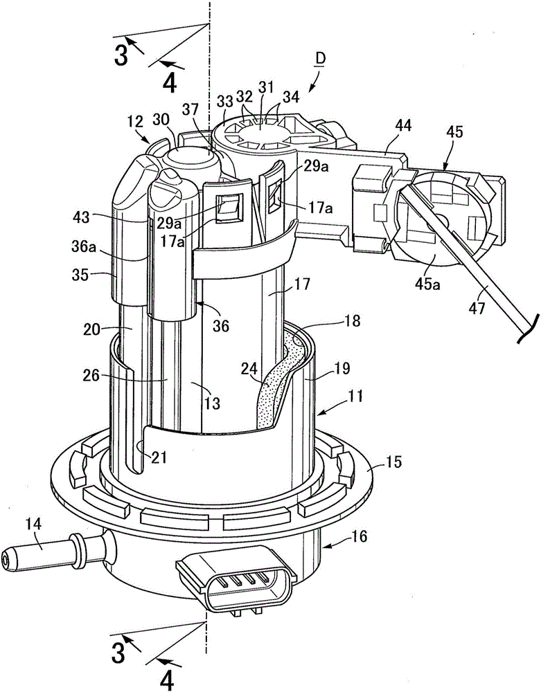
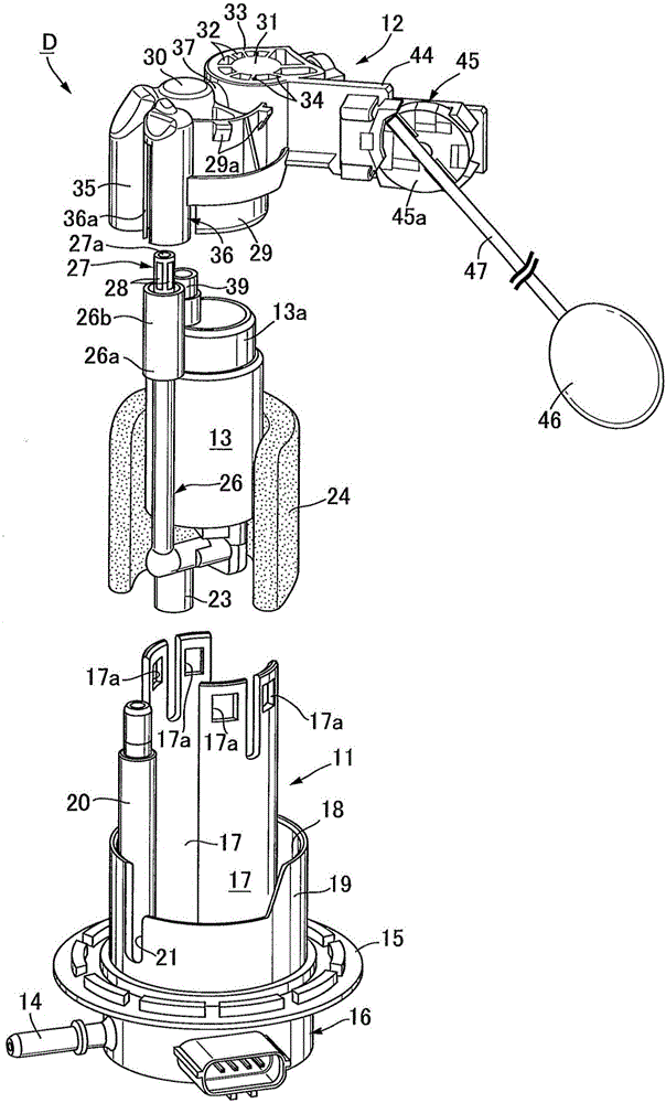
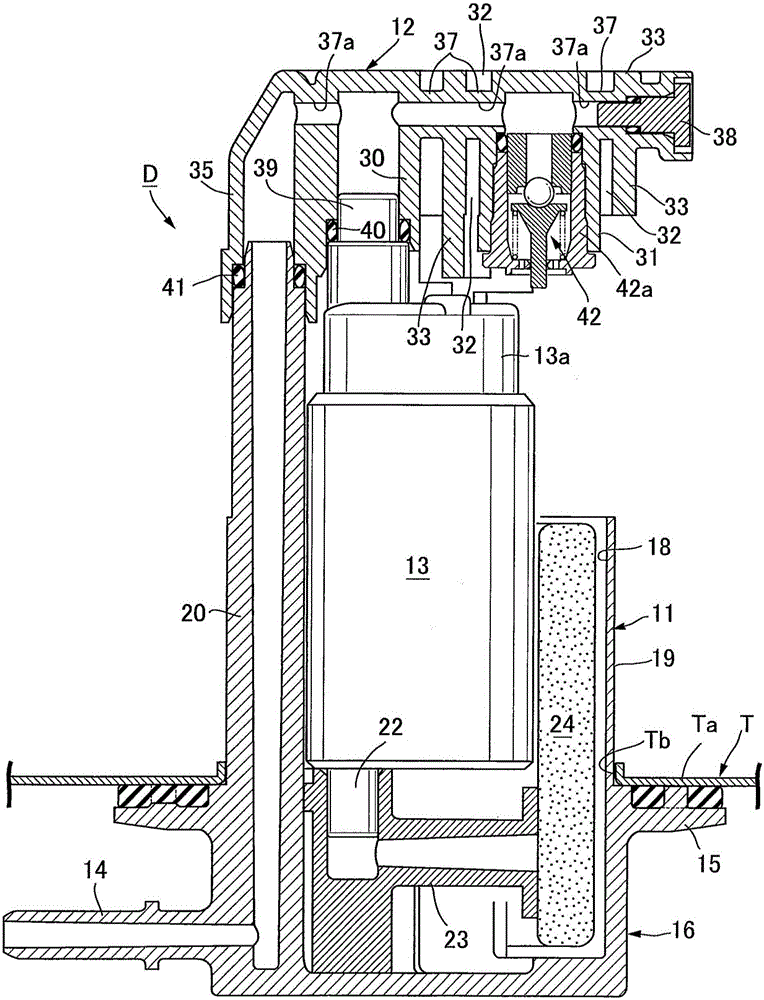
[0029] First of all, in Figure 1 ~ Figure 4 In the bottom plate Ta of the fuel tank T mounted on the vehicle (refer to image 3 with Figure 4 ), the fuel supply device D of the present embodiment that supplies the fuel in the fuel tank T to the fuel injection valve (not shown) of the engine is installed.

[0030] The fuel supply device D includes: a first housing 11 made of synthetic resin attached to the bottom plate Ta of the fuel tank T; a second housing made of synthetic resin connected to the first housing 11 and arranged in the fuel tank T Body 12; and a fuel pump 13 held between the first housing 11 and the second housing 12.

[0031] The first housing 11 is integrally formed with a bottomed cylindrical base portion 16 with a fuel take-out pipe 14 at the lower part and a mounting flange 15 mounted around the opening Tb of the bottom plate Ta of the fuel tank T at the upper pa...


PUM


Abstract

The invention provides a fuel supply apparatus by which the maximum liquid surface of fuel that when gas is sucked in a fuel pump from a vapor discharge channel when pores in a sucking filter are blocked can be adjusted without change on design of a filter apparatus. A surround wall, which encloses the periphery of the filter apparatus from overlook view, is formed on the upper part of the vapor discharge channel. An opening part is formed on the upper end or the side surface of the surround wall and is opened at the position bing higher than a lower end of the filter so as to communicate the internal spaces of the surround wall and the fuel pump. When the liquid level of fuel in the fuel tank is lower than the lower end of hte opening part, gas in the fuel tank is sucked into the fuel pump from the vapor discharge channel to cause adverse, thereby measuring pore blocking of the sucking filter in the fuel pump. The maximum liquid surface of fuel that when gas is sucked in a fuel pump from a vapor discharge channel when pores in a sucking filter are blocked can be adjusted just by simple change on design of height of the lower end of the opening part (the height of the upper end of hte surround wall), so that the structure, compared with design change of filter apparatus, is reduced in cost.

Description

Technical field [0001] The present invention relates to a fuel supply device, which has: a housing installed to block the opening of a fuel tank; and a fuel pump supported on the housing to remove fuel sucked from a suction port through a suction filter Ejected from the ejection port; a steam discharge hole, which is provided on the fuel pump, discharges the steam generated in the fuel; a steam discharge passage, one end of which is connected to the steam discharge hole and the other end extends to be higher than the steam A position above the discharge hole; and a filter device which is connected to the other end of the steam discharge passage and has a mesh filter on the outer peripheral surface. Background technique [0002] Such a fuel supply device is a known technology as disclosed in Patent Document 1. Patent Document 1 figure 1 with figure 2 The fuel supply device described is provided with a filter device 20 having a filter 58 made of a porous body at the upper end of ...

Claims


Application Information

Patent Timeline
Patent Type & Authority Applications(China)
IPC IPC(8): F02M37/20F02M37/22F02M37/10
CPCF02M37/10F02M37/20F02M37/22F02M37/50
Inventor 田村伸二铃木拓郎
Owner HITACHI ASTEMO LTD
Features
  • R&D
  • Intellectual Property
  • Life Sciences
  • Materials
  • Tech Scout
  • Unparalleled Data Quality
  • Higher Quality Content
  • 60% Fewer Hallucinations
Learn More