Stirring reaction still

The technology of stirring reaction kettle and stirring shaft is applied in the field of stirring reaction kettle, which can solve the problems of reducing the strength of stirring shaft, shortening the service life of stirring shaft, and incapable of fully mixing evenly, etc., and achieves the effect of improving utilization efficiency and improving service life.

Inactive Publication Date: 2015-10-21
何小平
View PDF4 Cites 10 Cited by
  • Summary
  • Abstract
  • Description
  • Claims
  • Application Information

AI Technical Summary

Problems solved by technology

[0002] The stirred reactor is a commonly used equipment in the production of chemical products. It is used to react and stir the materials in various forms. However, during the working process of the conventional stirred reactor, the kettle body and the stirring shaft are in a high temperature state, and the high temperature will cause the stirring shaft to Expansion, reducing the strength of the stirring shaft, thereby shortening the service life of the stirring shaft
Moreover, the stirring device in the current stirred reactor can only allow the raw materials to move in a small range when stirring, and the raw materials are continuously accumulated during the feeding process, and many raw materials sink to the bottom of the reactor body, which cannot be fully mixed evenly.

Method used


Image

  • Stirring reaction still

Examples


Embodiment Construction

[0010] The following will clearly and completely describe the technical solutions in the embodiments of the present invention with reference to the accompanying drawings in the embodiments of the present invention. Obviously, the described embodiments are only some, not all, embodiments of the present invention. Based on the embodiments of the present invention, all other embodiments obtained by persons of ordinary skill in the art without making creative efforts belong to the protection scope of the present invention.

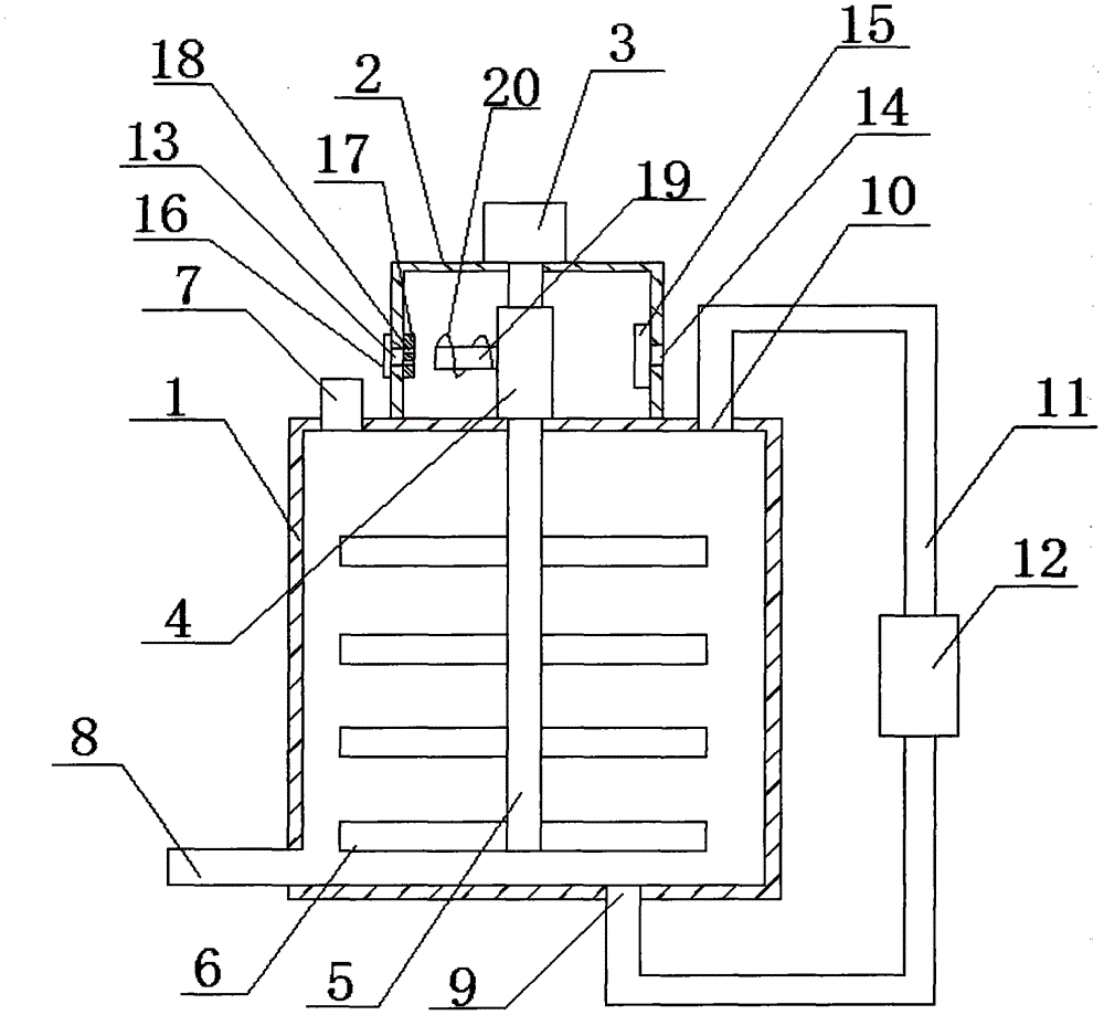
[0011] see figure 1 , in the embodiment of the present invention, a stirring reaction kettle includes a kettle body 1, a cover body 2 is provided in the middle of the upper end of the kettle body 1, a motor 3 is provided at the upper end of the cover body 2, and a shaft sleeve 4 is provided inside the cover body 2 , the output end of the motor 3 is provided with a stirring shaft 5 which passes through the cover body 2, the shaft sleeve 4 and the kettle body 1 ...


PUM


Abstract

The invention discloses a stirring reaction still which comprises a still body. A cover is arranged in the middle of the upper end of the still body, a motor is arranged at the upper end of the cover, a shaft sleeve is arranged in the cover, a stirring shaft sequentially penetrating through the cover, the shaft sleeve and the still body is arranged at the output end of the motor, and a plurality of stirring blades are evenly arranged on the stirring shaft. An air inlet is formed in the left side of the cover, an air outlet is formed in the right side of the cover, a water curtain is arranged on the air inlet, a mesh is formed in the middle of the water curtain, and a fan is arranged on the air outlet. An air guide shaft is arranged on one side of the shaft sleeve and exactly faces the air inlet, and a spiral air guide plate is spirally distributed on the outer wall of the air guide shaft in the axial direction. A flow guide inlet is formed in the right side of the upper end of the still body, a flow guide outlet is formed in the bottom end of the still body, a circulating pipeline is arranged between the flow guide outlet and the flow guide inlet, and a pump is arranged on the circulating pipeline. The stirring reaction still is simple in structure, convenient to use and good in stirring effect, the stirring shaft can be cooled, and the service life of the stirring shaft can be prolonged.

Description

technical field [0001] The invention relates to the technical field of chemical equipment, in particular to a stirring reaction kettle. Background technique [0002] The stirred reactor is a commonly used equipment in the production of chemical products. It is used to react and stir the materials in various forms. However, during the working process of the conventional stirred reactor, the kettle body and the stirring shaft are in a high temperature state, and the high temperature will cause the stirring shaft to Expansion, reducing the strength of the stirring shaft, thereby shortening the service life of the stirring shaft. Moreover, the stirring device in the current stirred reactor can only move the raw materials in a small range when stirring, and the raw materials are continuously accumulated during the feeding process, and many raw materials sink to the bottom of the reactor body, which cannot be fully mixed evenly. Contents of the invention [0003] The object of ...

Claims


Application Information

Patent Timeline
Patent Type & Authority Applications(China)
IPC IPC(8): B01J19/18
Inventor 何小平
Owner 何小平
Why Eureka
Try Eureka