Brake disc and method for producing same

A technology of brake discs and brake calipers, which is applied in the field of wear-reducing coatings and the manufacture of such brake discs, can solve the problems of expensive manufacturing and coating cracks, and achieve the effect of low cost and cheap manufacturing

Active Publication Date: 2019-01-04
ROBERT BOSCH GMBH
View PDF11 Cites 0 Cited by
  • Summary
  • Abstract
  • Description
  • Claims
  • Application Information

AI Technical Summary

Problems solved by technology

Such brake disks are relatively expensive to produce and have the disadvantage that cracks can develop in the coating due to the different expansion coefficients of the materials of the base disk and the wear-reducing coating when high temperature loads occur.
In addition, with known coating methods, the brake disc is subjected to thermal loads, which can lead to oxidation of the wear-reducing layer

Method used


Image

  • Brake disc and method for producing same
  • Brake disc and method for producing same
  • Brake disc and method for producing same

Examples


Embodiment Construction

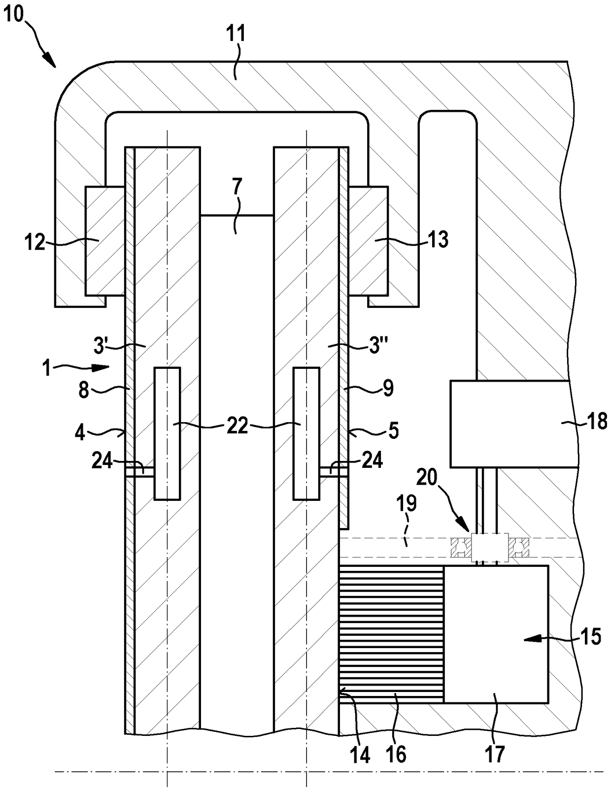
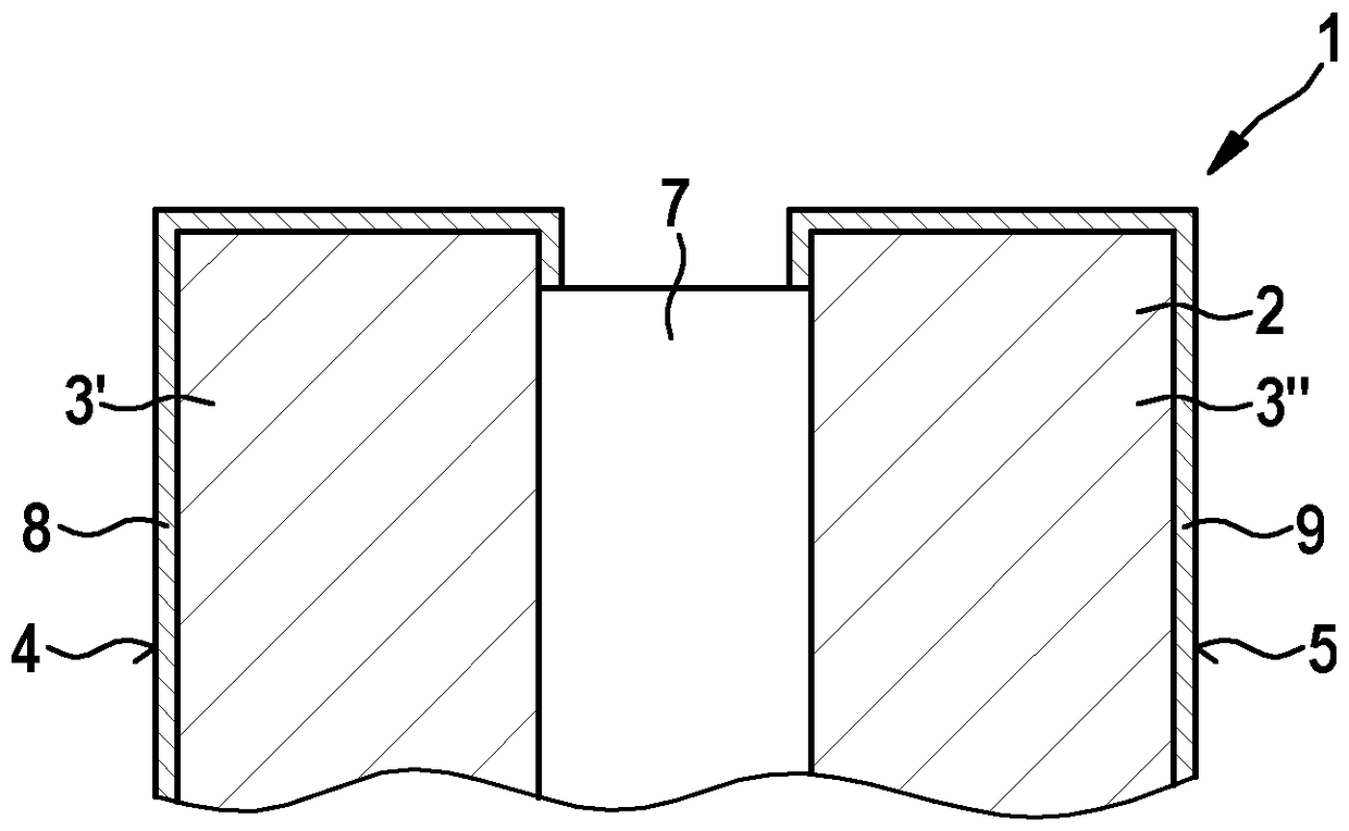
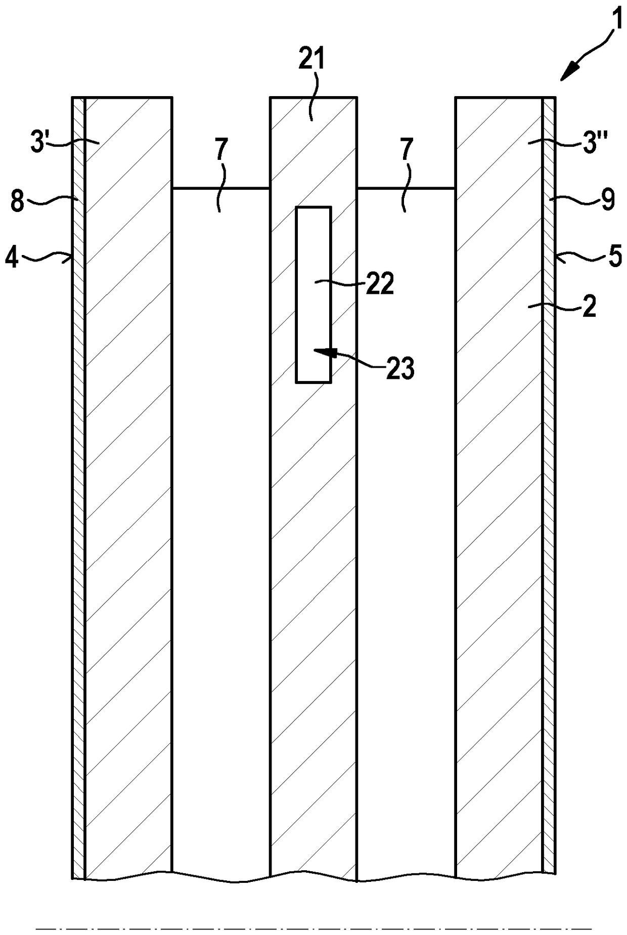
[0028] figure 1 A brake disk 1 for a motor vehicle (not shown) is shown in perspective. The brake disk 1 has a brake ring 3 which is formed by the base disk 2 . The braking ring 3 has a respective braking surface 4 or 5 on its two end faces. In the middle, the brake disk 1 has a mounting cup 6 for fastening the brake disk 1 to a wheel bearing or wheel of a motor vehicle. The support cup 6 can differ in terms of material from the brake ring and can be made of aluminum, for example. As a result, the unbounced mass is reduced and a more favorable heat transfer to the hub and rim is achieved. A plurality of bores for screw connections for fastening are formed on the support pot 6 . The braking surfaces 4 , 5 are subject to wear during operation, which has the consequence that the brake disk 1 must be replaced periodically. Today's brake discs are usually made of gray cast iron and some also of ductile iron or cast from suitable steel alloys and are thus machined by turning. ...


PUM


Abstract

The invention relates to a brake disc (1), in particular for a motor vehicle, comprising a base disc (2) of a first material and a wear-reducing coating (8,9) of a second material. According to the invention, it is provided that the first material is a lightweight metal and the second material is an oxide layer (8,9).

Description

technical field [0001] The invention relates to a brake disk, in particular for a motor vehicle, having a base disk made of a first material and having a wear-reducing coating made of a second material. [0002] Furthermore, the invention relates to a brake device for a motor vehicle with a brake disc connectable / connectable to a wheel and with a brake caliper associated with the brake disc, which has at least one Steerable brake elements. [0003] Furthermore, the invention relates to a method for producing such a brake disk. Background technique [0004] Conventional braking systems of motor vehicles have at least one brake disk assigned to each wheel, which can be clamped between two brake pads of a brake caliper for generating a braking torque. During clamping, friction occurs between the brake pad and the brake disc, which friction generates heat. The generated heat is at least partially stored in the brake disc. In extreme cases, such as when braking from high spee...

Claims


Application Information

Patent Timeline
Patent Type & Authority Applications(China)
IPC IPC(8): F16D65/12
CPCC23C8/10C23C8/36C25D11/026C25D11/04C25D11/26C25D11/30F16D65/125F16D65/127F16D65/128F16D2065/781F16D2200/003F16D2200/0039F16D2250/0038F16D2250/0046F16D55/225F16D2200/0043
Inventor S.多琳I.波塔彭科
Owner ROBERT BOSCH GMBH
Why Eureka
Try Eureka