Delay detonation control circuit

A technology for controlling circuits and switching circuits, applied in electric fuzes, weapon accessories, fuzes, etc., can solve problems such as inability to achieve good blasting effects, high prices, and restrictions on purchase and use

Active Publication Date: 2015-11-11
成都天博威科技有限公司
View PDF6 Cites 10 Cited by
  • Summary
  • Abstract
  • Description
  • Claims
  • Application Information

AI Technical Summary

Problems solved by technology

[0003] With the continuous improvement of domestic blasting theory and technology, time-delay blasting has been widely used. However, the above-mentioned several time-delay detonators have the following technical problems in practical application: (1) The prompt detonator is compatible with the fixed-stage time-delay detonator. In combination, when encountering different hole depths or complex geological environments, there is often no suitab...

Method used


Image

  • Delay detonation control circuit
  • Delay detonation control circuit
  • Delay detonation control circuit

Examples


Embodiment Construction

[0030] Below in conjunction with accompanying drawing and specific embodiment the present invention is described in further detail:

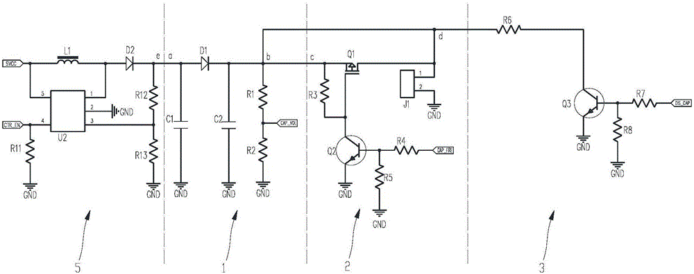
[0031] combine figure 1 As shown, the delayed detonation control circuit includes a charging circuit 1, a discharging circuit 2, a protection circuit 3 and a functional circuit 4; wherein,

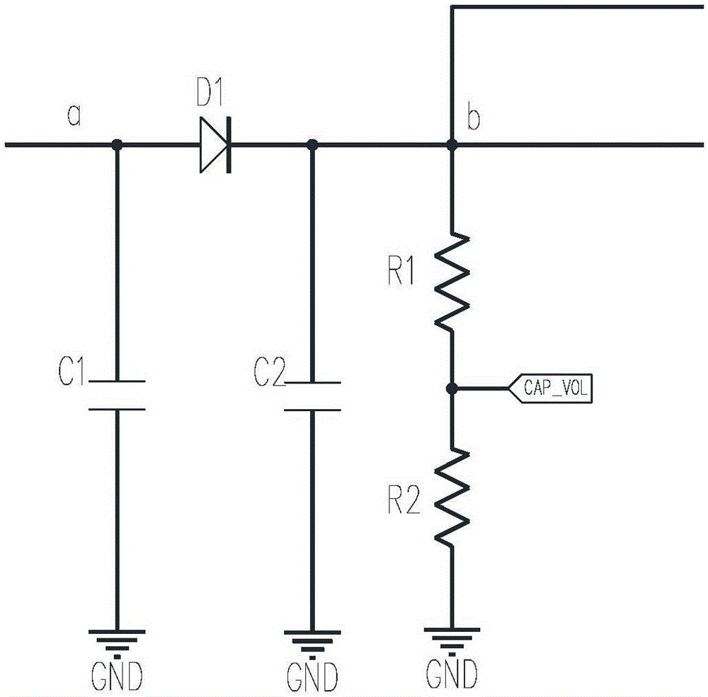
[0032] The charging circuit 1 includes an energy storage element; the charging circuit 1 is configured to receive an input current and store energy through the energy storage element;

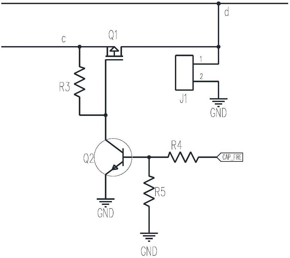
[0033] The discharge circuit 2 includes a first switch circuit for connecting the electric detonator; and when the first switch circuit is turned on, the energy stored in the energy storage element is discharged into the electric detonator through the first switch circuit;

[0034] The protection circuit 3 includes a second switch circuit; and when the first switch circuit is in an off state, the second switch circuit is turned on, and the energy stored in the energy storage...


PUM


Abstract

The invention discloses a delay detonation control circuit. The delay detonation control circuit comprises a charging circuit, a discharging circuit, a protection circuit and a function circuit. The charging circuit comprises an energy storage element used for carrying out energy storage after current signals are received. The discharging circuit comprises a first switch circuit used for being connected with an electric detonator, and when the first switch circuit is conducted, energy stored in the energy storage element is released to the electric detonator through the first switch circuit, and the remote detonation control over a short electric detonator is achieved. The function circuit comprises a programmable device through which the delay conduction time of the first switch circuit can be flexibly set, and the delay precision is high. In addition, the protection circuit further comprises a second switch circuit. When the first switch circuit is in a stop state, the second switch circuit is conducted, the energy stored in the energy storage element is released through the second switch circuit, and the electric detonator is effectively prevented from being mistakenly triggered when the first switch circuit is in the stop state.

Description

technical field [0001] The invention relates to a delay detonation control circuit. Background technique [0002] At present, the detonators used in China include electric detonators and nonel detonators. Among them, according to the delay function, the electric detonator is divided into instantaneous detonator, fixed segment delay electric detonator and electronic digital detonator, etc., and the nonel detonator is divided into prompt nonel detonator and fixed segment delay nonel detonator. . The fixed-level delay detonator is a delay function realized by adding other delay bodies on the basis of the instant detonator. Due to the error of the delay body, its accuracy is difficult to guarantee. At the same time, due to the constraints of production factors, only fixed-rank products can be produced. The electronic digital detonator is to package the electronic chip and the detonator together. Through online programming during construction, each detonator is given specific ...

Claims


Application Information

Patent Timeline
IPC IPC(8): F42C11/06F42C19/12
Inventor 代绪慧高文乐魏东周奥博
Owner 成都天博威科技有限公司
Why Eureka
Try Eureka