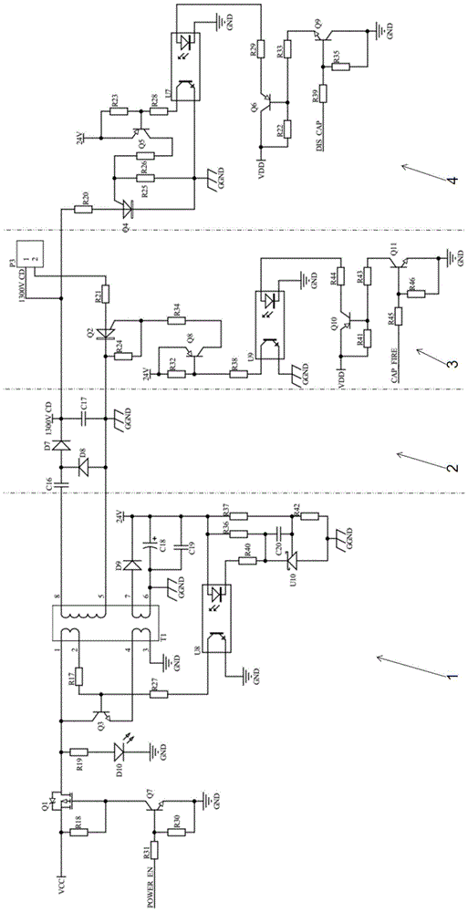
A high-voltage excitation delay detonation control circuit

A control circuit, high-voltage charging technology, applied in blasting, electric fuze, weapon accessories and other directions, can solve the problems of difficult to guarantee accuracy, no circuit, reduce the reliability of network connection, etc., to achieve high delay accuracy and achieve safety. Effect

Inactive Publication Date: 2017-02-01
成都天博威科技有限公司
View PDF4 Cites 0 Cited by
  • Summary
  • Abstract
  • Description
  • Claims
  • Application Information

AI Technical Summary

Problems solved by technology

The non-electric blasting network that generally adopts under the interweaving of these two situations has the following problems: (1) the current nonel detonators are divided into prompt detonator detonators and fixed segment delay nonel detonators; The segment delay nonel detonator is based on the instant nonel detonator plus the delay function realized by the physical delay body. Due to the error of the delay body, its accuracy is difficult to guarantee. At the same time, due to the constraints of production factors, Only products with fixed segments can be produced, which makes it impossible to arbitrarily delay each hole according to the theoretical design in the application process to achieve the ideal effect of delayed blasting; (2) most of the current non-electric blasting networks are detonation The tubes are connected by connecting devices, and the entire network has no circuits, so it is impossible to use instruments to detect before detonation, which virtually reduces the reliability of network connections

Method used


Image

  • A high-voltage excitation delay detonation control circuit
  • A high-voltage excitation delay detonation control circuit
  • A high-voltage excitation delay detonation control circuit

Examples


Embodiment Construction

[0028] Below in conjunction with accompanying drawing and specific embodiment the present invention is described in further detail:

[0029] to combine figure 1 As shown, a high-voltage excitation delay detonation control circuit includes a boost circuit 1, a high-voltage charging circuit 2, a high-voltage discharging circuit 3, a protection circuit 4 and a functional circuit; wherein,

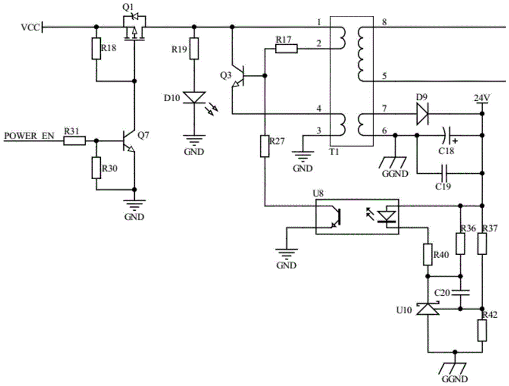
[0030] The boosting circuit 1 includes a transformer element T1; the boosting circuit is configured to receive an input low-voltage signal, and use the transformer element T1 to boost the low-voltage signal to a required high-voltage signal;

[0031] The high voltage in the present invention refers to a voltage greater than or equal to 1300V to meet the excitation requirements of the high-voltage excitation needle;

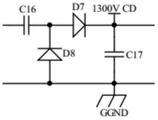
[0032] The high-voltage charging circuit 2 includes a high-voltage energy storage element; the high-voltage charging circuit is configured to receive the current input from the b...


PUM


Abstract

The invention discloses a control circuit for high-voltage excitation delay detonating. The control circuit comprises a voltage booster circuit, a high-voltage charging circuit, a high-voltage discharging circuit, a protection circuit and a functional circuit. The voltage booster circuit is used for converting a low-voltage signal into a high-voltage signal needed by a high-voltage excitation needle. The high-voltage charging circuit is used for receiving currents input from the voltage booster circuit and storing energy. The high-voltage discharging circuit comprises a first switch circuit. When the first switch circuit is switched on, energy is released into the high-voltage excitation needle through the first switch circuit, and a detonating tube can be detonated through remote control. In addition, the protection circuit comprises a second switch circuit. When the first switch circuit is switched off, the second switch circuit is switched on, the energy stored in a high-voltage energy storage element is released through the second switch circuit, and therefore potential safety hazards in the detonating tube connection process are reduced. The functional circuit comprises a programmable device. The delay time is set through the programmable device, and the first switch circuit is triggered to be switched on after the delay time.

Description

technical field [0001] The invention belongs to the technical field of blasting, and in particular relates to a high-voltage excitation delay initiation control circuit. Background technique [0002] With the continuous improvement of domestic blasting theory and technology, delayed blasting has been widely used. In particular, the development of electronic digital detonators, its arbitrary setting of delay and high accuracy has greatly promoted the transformation of delay blasting theory into practical effects; but on the other hand, with the requirements of safety and networking, It has also become an inevitable trend for non-electric blasting networks to gradually replace electric networks. The non-electric blasting network that generally adopts under the interweaving of these two situations has the following problems: (1) the current nonel detonators are divided into prompt detonator detonators and fixed segment delay nonel detonators; The segment delay nonel detonator...

Claims


Application Information

Patent Timeline
Patent Type & Authority Patents(China)
IPC IPC(8): F42D1/05F42C11/06
CPCF42C11/06F42D1/05
Inventor 代绪慧高文乐魏东罗衍涛周奥博
Owner 成都天博威科技有限公司
Why Eureka
Try Eureka