Power convertor, motor driver equipped with power convertor, blower and compressor equipped with motor driver, and air conditioner, refrigerator, and freezer equipped with blower and compressor

A technology for power conversion devices and blowers, which is applied in the field of power conversion devices and motor drive devices, can solve problems such as the complexity of control software, and achieve the effect of high precision and extended detection period

Active Publication Date: 2015-11-18
MITSUBISHI ELECTRIC CORP
View PDF3 Cites 0 Cited by
  • Summary
  • Abstract
  • Description
  • Claims
  • Application Information

AI Technical Summary

Problems solved by technology

In the structure where the shunt resistance of the power supply or the shunt resistance of the lower arm is provided, the control software is complicated because the detected phase current needs to be determined for each phase

Method used


Image

  • Power convertor, motor driver equipped with power convertor, blower and compressor equipped with motor driver, and air conditioner, refrigerator, and freezer equipped with blower and compressor
  • Power convertor, motor driver equipped with power convertor, blower and compressor equipped with motor driver, and air conditioner, refrigerator, and freezer equipped with blower and compressor
  • Power convertor, motor driver equipped with power convertor, blower and compressor equipped with motor driver, and air conditioner, refrigerator, and freezer equipped with blower and compressor

Examples


Embodiment approach 1

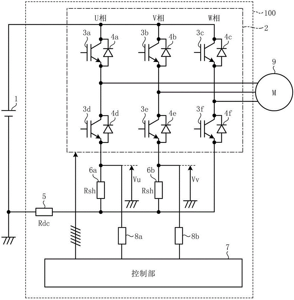
[0058] figure 1 is a diagram showing an example of the configuration of the power conversion device according to the first embodiment. exist figure 1In the example shown, the power conversion device 100 according to Embodiment 1 is configured to convert the DC power supplied from the DC power supply 1 into figure 1 In the example shown is a 3-phase alternating current supplied by an electric motor 9 .

[0059] Such as figure 1 As shown, the power conversion device 100 has the following main components for supplying 3-phase AC power to the motor 9: an inverter 2, which is composed of 3 bridge arms, and the 3 bridge arms include: an upper bridge arm switching element 3a to 3c (here, 3a: U phase, 3b: V phase, 3c: W phase) and lower arm switching elements 3d to 3f (here, 3d: U phase, 3e: V phase, 3f: W phase); and a control section 7. It generates six drive signals corresponding to the upper arm switching elements 3a to 3c of each phase and the lower arm switching elements 3d ...

Embodiment approach 2

[0129] In Embodiment 1, the method of connecting the lower arm shunt resistors to the lower arm switching elements of the two phases in the U phase, the V phase, and the W phase, and connecting the lower arm switching elements of the two phases arm voltage is detected to calculate the phase currents iu, iv, and iw flowing into the load device. However, in this embodiment, the following method will be described. and the lower arm switching elements of each phase of the W phase are connected, the lower arm voltages of these three phases are detected, and the currents iu, iv, and iw of each phase flowing into the load device are calculated.

[0130] Figure 11 It is a figure which shows one structural example of the power conversion apparatus concerning Embodiment 2. In addition, the same code|symbol is attached|subjected to the same or equivalent structural part as Embodiment 1, and detailed description is abbreviate|omitted.

[0131] In addition to the structure of Embodiment...


PUM


Abstract

The purpose of the present invention is to provide a power convertor capable of highly accurate control based on a current in each phase by extending the detection period of the current in each phase without increasing the size of a device and incurring high cost. The power convertor comprises: a power source shunt resister (5) provided in between the negative voltage side of a DC power source (1) and an inverter (2); and per-phase lower-arm shunt resistors (6a, 6b) respectively provided in between two of three per-phase lower-arm switching elements (3d, 3e) and the power source shunt resister (5). The power convertor detects the voltages between the connection points for the per-phase lower-arm switching elements (3d, 3e) and per-phase lower-arm shunt resistors (6a, 6b), and the negative voltage side of the DC power source (1), and calculates the per-phase current flowing in a load device (9) on the basis of each detected value.

Description

technical field [0001] The present invention relates to a power conversion device, a motor drive device including the same, a blower and a compressor including the same, and an air conditioner, a refrigerator, and a refrigerator including these. Background technique [0002] In a power conversion device, for example, the phase current flowing in a 3-phase load such as a motor is detected, and the load is controlled based on the current of each phase. The ON / OFF state of the switching element of the inverter is combined to generate a 3-phase AC voltage and supply it to the load. [0003] As a method of detecting each phase current flowing into a three-phase load, there is a method of providing a current sensor or a shunt resistor connected in series to a switching element constituting an inverter. As a structure for installing a shunt resistor, there are: a structure for installing a power supply shunt resistor for detecting the current between the DC power supply and the in...

Claims


Application Information

Patent Timeline
Patent Type & Authority Applications(China)
IPC IPC(8): H02M7/5387
CPCH02M7/53875H02M2001/0009H02M2007/53876H02M7/53873H02P27/06H02M1/0009H02M7/53876H02M7/53871
Inventor 植村启介下麦卓也有泽浩一筱本洋介梅原成雄浦慎一郎谷川诚
Owner MITSUBISHI ELECTRIC CORP
Why Eureka
Try Eureka