
Power conversion devices, motor drives, blowers, compressors, air conditioners, and refrigerators

A power conversion device and power conversion technology, which is applied in the field of power conversion devices and motor drive devices, can solve problems such as narrow ranges, and achieve the effect of expanding the detection period and suppressing switching losses

Active Publication Date: 2018-09-04
MITSUBISHI ELECTRIC CORP
View PDF9 Cites 0 Cited by
  • Summary
  • Abstract
  • Description
  • Claims
  • Application Information

AI Technical Summary

Problems solved by technology

That is, within one switching cycle, the period for detecting the current of each phase is limited to a narrow range

Method used


Image

  • Power conversion devices, motor drives, blowers, compressors, air conditioners, and refrigerators
  • Power conversion devices, motor drives, blowers, compressors, air conditioners, and refrigerators
  • Power conversion devices, motor drives, blowers, compressors, air conditioners, and refrigerators

Examples


Embodiment approach 1

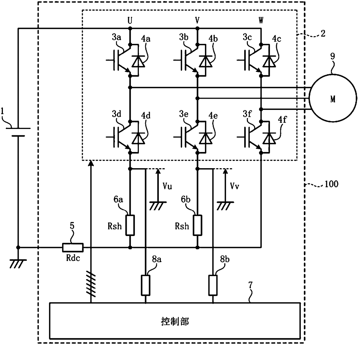
[0053] figure 1 is a diagram showing an example of the configuration of the power conversion device according to the first embodiment. In the example shown in FIG. 1 , power conversion device 100 according to Embodiment 1 is configured to convert DC power supplied from DC power supply 1 into figure 1 The example shown is three-phase AC power supplied by an electric motor 9.

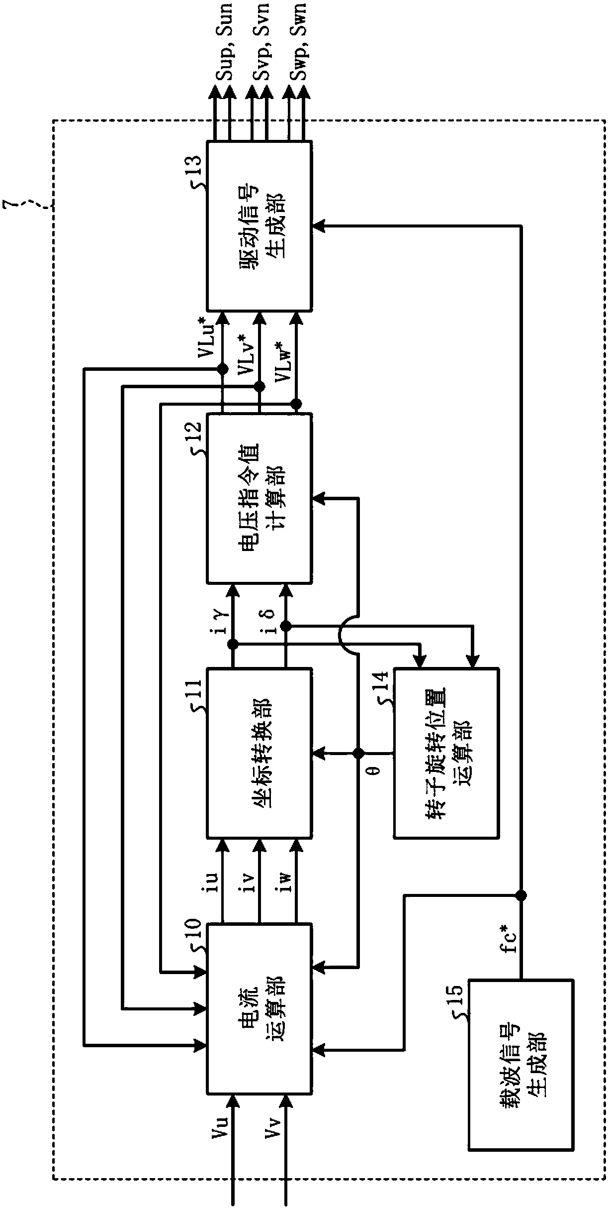
[0054] Such as figure 1As shown, the power conversion device 100, as a main structural element for supplying three-phase AC power to the motor 9, includes an inverter 2 composed of three arms including an upper arm switching element 3a to 3c (here, 3a: U phase, 3b: V phase, 3c: W phase) and lower arm switching elements 3d to 3f (here, 3d: U phase, 3e: V phase, 3f: W phase ); and the control section 7, which generates 6 drive signals corresponding to the upper bridge arm switching elements 3a to 3c of each phase and the lower bridge arm switching elements 3d to 3f of each phase, and sends them to the up...

Embodiment approach 2

[0136] In Embodiment 1, a method is described in which the lower arm shunt resistor is connected to the lower arm switching elements of two phases of the U phase, the V phase, and the W phase, and the lower arm voltages of these two phases are detected. This is to calculate the phase currents iu, iv, and iw flowing through the load device, but in this embodiment, the following method will be described. The arm switching elements are connected, and these three-phase lower bridge arm voltages are used to calculate the currents iu, iv, and iw of each phase flowing through the load device.

[0137] Figure 12 It is a figure which shows one structural example of the power conversion apparatus concerning Embodiment 2. In addition, the same code|symbol is attached|subjected to the same or equivalent structural part as Embodiment 1, and detailed description is abbreviate|omitted.

[0138] In addition to the structure of Embodiment 1, the power conversion device 100a according to Emb...


PUM


Abstract

The present invention provides a power conversion conversion device, which includes: an inverter (2), which consists of a bridge with upper arm switching elements (3a to 3c) of each phase and lower arm switching elements (3d to 3f) of each phase The arms are connected in parallel; the power supply shunt resistor (5), which is arranged between the negative voltage side of the DC power supply (1) and the inverter; the lower bridge arm shunt resistors (6a, 6b), which are at least two The switching elements of the lower bridge arm of each phase and the shunt resistors of the power supply are arranged separately; the voltage detection part (8a, 8b) detects the negative voltage side of the DC power supply and each connection point of the switching elements of the lower bridge arm of each phase and the shunt resistors of the lower bridge arm. and the control unit (7), which generates drive signals corresponding to the switching elements of the upper arm of each phase and the switching elements of the lower arm of each phase according to the detection values ​​of the voltage detecting unit, wherein the above-mentioned power conversion The conversion device changes the ratio of the time during which all the switching elements of the upper arm are in the ON state to the time during which all the switching elements of the lower arm are in the ON state within one cycle of switching by the inverter.

Description

technical field [0001] The present invention relates to a power conversion device, a motor drive device including the same, a blower and a compressor including the same, and an air conditioner, a refrigerator, and a refrigerator including the same. Background technique [0002] In a power conversion device that generates a three-phase AC voltage and supplies it to a load by combining the on / off (ON / OFF) states of the switching elements constituting a three-phase inverter of a PWM modulation method, for example, detecting the voltage flowing through a motor The current of each phase of the three-phase load is equal, and the load is controlled based on the current of each phase. [0003] As means for detecting the currents of the respective phases flowing through the three-phase load, there are, for example, current sensors and shunt resistors connected in series to switching elements constituting the inverter. [0004] As a structure for installing a shunt resistor, for exam...

Claims


Application Information

Patent Timeline
Patent Type & Authority Patents(China)
IPC IPC(8): F25B31/02H02P21/18F24F7/06F24F1/00H02M7/537H02P27/08F24F7/007H02M7/5387F25D17/06
CPCH02M7/5387H02P21/18F25D17/062F25D2317/0681Y02B70/10H02M1/0009H02M1/0048H02M7/53876F24F1/0018F24F7/007F24F7/06F25B31/02H02M7/537H02P27/08
Inventor 植村启介下麦卓也有泽浩一筱本洋介梅原成雄浦慎一郎谷川诚
Owner MITSUBISHI ELECTRIC CORP
Learn More