Power supply system, vehicle provided with the same, power supply system control method and computer-readable recording medium bearing program for causing computer to control the power supply system

a technology of power supply system and control method, which is applied in the direction of battery/fuel cell control arrangement, dc-ac conversion without reversal, battery/fuel cell propulsion, etc., to achieve the effect of reducing resistance loss, and suppressing loss in the whole power supply system

Active Publication Date: 2009-07-23
TOYOTA JIDOSHA KK
View PDF24 Cites 22 Cited by
  • Summary
  • Abstract
  • Description
  • Claims
  • Application Information

AI Technical Summary

Benefits of technology

[0023]According to the invention, the first voltage converting device is arranged between the first power storage device and the load device, and the second voltage converting device is arranged between the second power storage device and the load device. Thus, the first and second voltage converting devices are connected in parallel to the load device, convert the voltages provided from the corresponding power storage devices and provide them to the load device, respectively. A resistance loss in the power storage device is proportional to the square of the current. When the power required of the power supply system is small, the switching loss in the voltage converting device is relatively larger than the resistance loss in the power storage device. Accordingly, by reducing the number of the voltage converting devices to be operated, the loss in the whole power supply system can be suppressed. When the required power is large, the resistance loss can be reduced by operating both the first and second voltage converting devices to distribute the load to the first and second power storage devices. Thereby, the loss in the whole power supply system can be suppressed. In this invention, therefore, the control unit performs the control such that one of the first and second voltage converting devices operates and the other stops, when the required power is smaller than the reference value. Also, it performs the control such that both the first and second voltage converting devices operate, when the required power is equal to or larger than the reference value. In this invention, therefore, the loss in the power supply system can be suppressed.

Problems solved by technology

However, the above Japanese Patent Laying-Open No. 2003-209969 has merely disclosed that the plurality of power supply stages are connected in parallel and are operated to charge and discharge uniformly the plurality of batteries included in each of the power supply stages, and has not particularly discussed a method of controlling each power supply stage for suppressing a loss in the whole power supply control system.

Method used


Image

  • Power supply system, vehicle provided with the same, power supply system control method and computer-readable recording medium bearing program for causing computer to control the power supply system
  • Power supply system, vehicle provided with the same, power supply system control method and computer-readable recording medium bearing program for causing computer to control the power supply system
  • Power supply system, vehicle provided with the same, power supply system control method and computer-readable recording medium bearing program for causing computer to control the power supply system

Examples


first embodiment

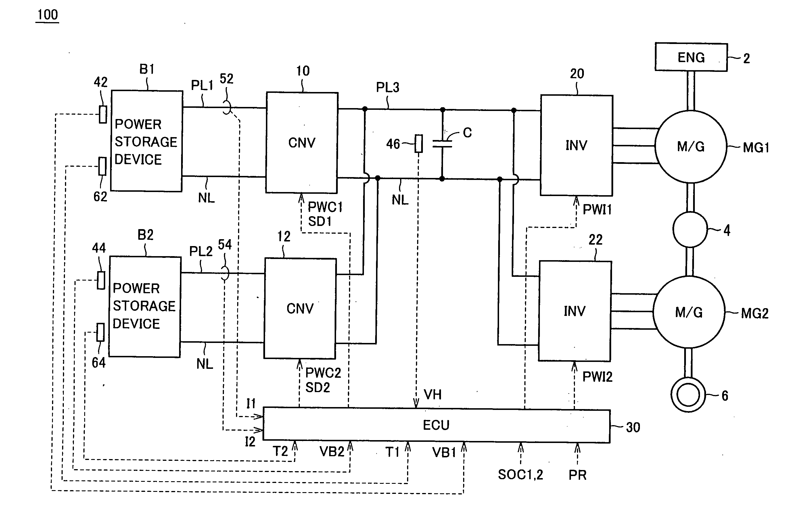
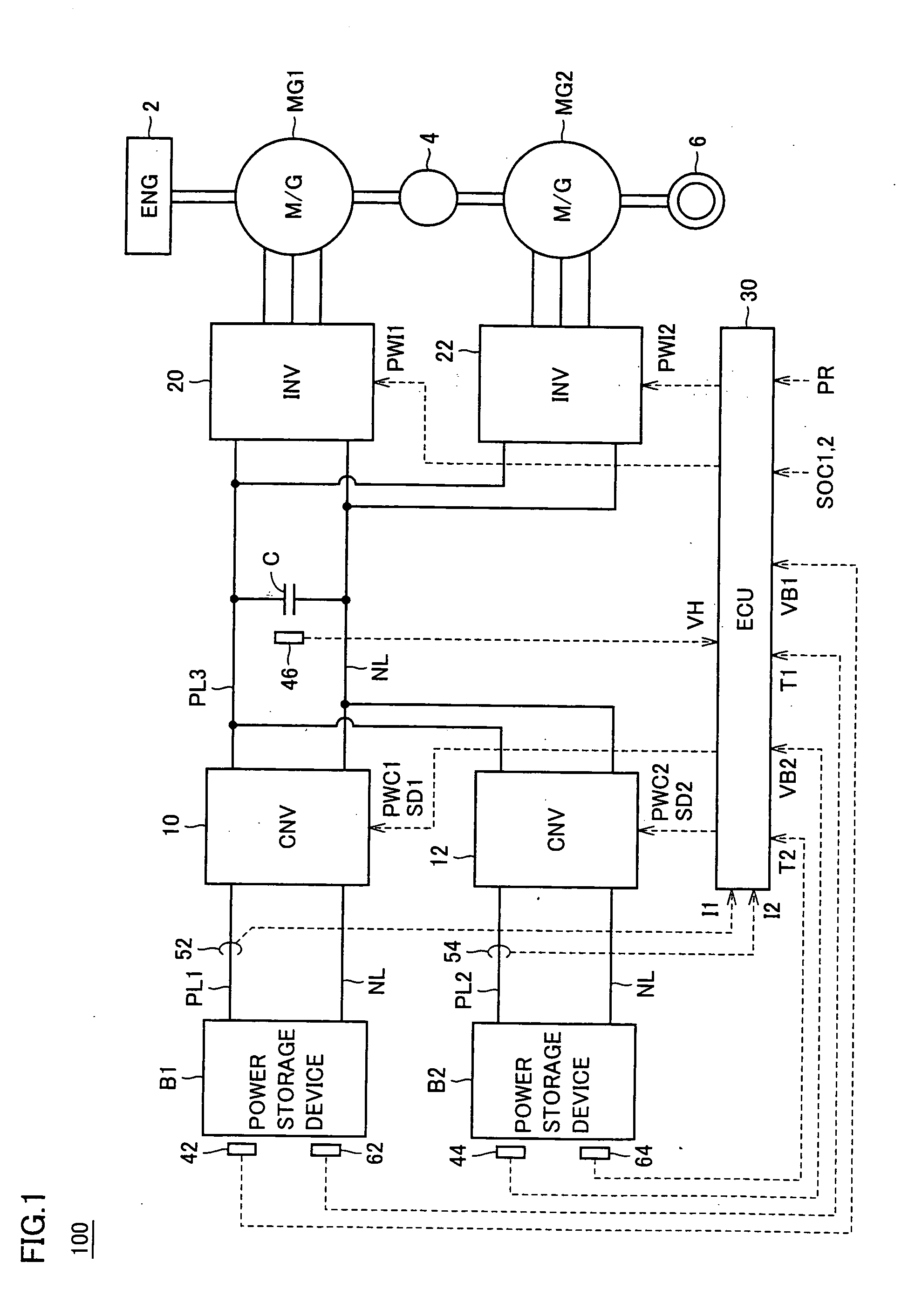
[0041]FIG. 1 is a whole block diagram of a hybrid vehicle which is shown as an example of a vehicle carrying a power supply system according to the invention. Referring to FIG. 1, a hybrid vehicle 100 includes an engine 2, motor generators MG1 and MG2, a power split device 4 and wheels 6. Hybrid vehicle 100 also includes power storage devices B1 and B2, converters 10 and 12, a capacitor C, inverters 20 and 22, and an ECU (Electronic Control Unit) 30. Further, hybrid vehicle 100 includes voltage sensors 42, 44 and 46, current sensors 52 and 54, and temperature sensors 62 and 64.

[0042]Hybrid vehicle 100 runs using engine 2 and motor generator MG2 as power sources. Power split device 4 is coupled between engine 2 and motor generators MG1 and MG2 for distributing the power to them. Power split device 4 is formed, e.g., of a planetary gear mechanism having three rotation axes, i.e., a sun gear, a planetary carrier and a ring gear, and these three rotation axes are connected to rotation a...

second embodiment

[0089]In a second embodiment, reference value Pth used for determining whether one of converters 10 and 12 is to be stopped or not is variable according to the temperature of power storage devices B1 and B2.

[0090]FIG. 9 shows a relationship between the temperature and the internal resistance of the power storage device, and FIG. 10 shows a relationship between required power PR and the resistance loss in power storage devices B1 and B2. Referring to FIG. 9, the internal resistance of the power storage device increases with decrease in temperature of the power storage device. Referring to FIG. 10, the resistance loss in the power storage device increases with increase in required power. Since the internal resistance increases with decrease in temperature of the power storage device as described above, the resistance loss in the power storage device further increases with decrease in temperature of the power storage device.

[0091]In FIG. 7 showing the total loss in the power supply sys...

third embodiment

[0096]In a third embodiment, reference value Pth is variable according to a State of Charge (SOC) of power storage devices B I and B2 taking a value between 0% and 100%.

[0097]FIG. 12 shows a relationship between the SOC and the internal resistance of the power storage device. FIG. 13 shows a relationship between required power PR and the resistance loss in power storage devices B1 and B2. Referring to FIG. 12, the internal resistance of the power storage device increases with decrease in SOC of the power storage device. Referring to FIG. 13, the resistance loss in the power storage device increases with increase in required power. Since the internal resistance increases with decrease in SOC as described above, the resistance loss in the power storage device further increases with decrease in SOC of the power storage device.

[0098]Therefore, it is preferable to decrease reference value Pth as the SOC of power storage devices B1 and B2 decreases, similarly to the second embodiment. FIG...


PUM


Abstract

First and second converters are connected in parallel to positive and negative lines, respectively. When a required power is smaller than a reference value, an ECU controls the first and second converters such that one of the first and second converters operates and the other stops. When the required power is equal to or larger than the reference value, the ECU controls the first and second converters such that both the first and second converters operate.

Description

TECHNICAL FIELD[0001]The present invention relates to a control technique for suppressing a loss in a power supply system provided with a plurality of power storage devices.BACKGROUND ART[0002]Japanese Patent Laying-Open No. 2003-209969 has disclosed a power supply control system provided with a plurality of power supply stages. This power supply control system includes a plurality of power supply stages that are connected in parallel together and supply a DC power to at least one inverter. Each power supply stage includes a battery and a boost / back-boost DC-DC converter.[0003]In this power supply control system, the plurality of power supply stages are controlled such that a plurality of batteries included in each of the power supply stages are uniformly charged and discharged to maintain an output voltage for the inverter.[0004]However, the above Japanese Patent Laying-Open No. 2003-209969 has merely disclosed that the plurality of power supply stages are connected in parallel and...

Claims


Application Information

Patent Timeline
Patent Type & Authority Applications(United States)
IPC IPC(8): B60W10/04H02J1/00B60W20/00B60L50/15B60L50/16
CPCB60K6/26Y02T10/6217B60K6/445B60L11/1868B60W10/08B60W20/00Y02T10/6239Y02T10/7005Y02T10/7066B60L11/123B60L11/14B60L11/1864B60L2210/10B60L2210/30B60L2210/40Y02T10/7077Y02T10/7241Y02T10/7061Y02T10/7216B60K6/28B60L15/2045B60L50/16B60L50/61B60L58/20B60L58/21Y02T10/62Y02T10/64Y02T10/70Y02T10/7072Y02T10/72H02M3/155H02M7/48B60W20/10
Inventor OYOBE, HICHIROSAIANG, WANGLENGICHIKAWA, SHINJIYOSHIDA, HIROSHISAWADA, HIROKI
Owner TOYOTA JIDOSHA KK
Why Eureka
Try Eureka