Hybrid air/magnetic core inductor

a technology of inductor and magnetic core, which is applied in the direction of inductance, inductance with magnetic core, transformer/inductance details, etc., can solve the problems of complex winding design, increase core temperature, and core heat may be trapped inside such a complex winding, so as to reduce winding cost and/or loss, reduce core cost, and improve cooling

Inactive Publication Date: 2007-04-17
EATON INTELLIGENT POWER LTD
View PDF18 Cites 21 Cited by
  • Summary
  • Abstract
  • Description
  • Claims
  • Application Information

AI Technical Summary

Benefits of technology

[0006]According to some embodiments of the invention, an inductor includes an elongate magnetic core. A coil is wrapped around the core. A spacer separates the coil from the core to provide a coolant passage between the coil and the core. For example, the coolant passage may comprise an air passage extending substantially parallel to an axis of the core and having first and second openings proximate respective first and second ends of the core. The coil may include a twisted bundle of individually insulated conductors, which can reduce skin effect and / or proximity effect losses. The inductor may be housed in a flux-tolerant compartment, i.e., a conductive aluminum structure that supports eddy currents with acceptably low resistive losses.
[0010]Potential advantages of some embodiments of the present invention include reduced core costs and lower winding cost and / or losses. Provision of a coolant passage between the core and the coil can provide better cooling and can reduce thermal coupling between the core and the coil. Use of a twisted bundle of conductors can reduce skin and proximity effect losses. Inductors according to some embodiments of the invention may be optimally paired to reduce far field intensity and enhance net inductance.

Problems solved by technology

Torroidal designs may require a complex winding design, and core heat may be trapped inside such a complex winding.
Winding heat may further add to core temperature, and inner winding layers may be difficult to keep cool in such designs.
Difficulties in cooling often drives toward the use of a ferrite core, which may be costly due to higher core volume.
Simple air core designs may occupy a large volume to achieve a desired inductance, which can lead to high coil resistance and losses.
Multiple layers can amplify skin and proximity effect losses and can impede cooling of inner layers.
Losses often exceed acceptable levels, and the return flux path (thru surrounding air) may adversely affect nearby items.
Escaping radiated fields may elevate EMI levels, and adjacent sensitive electronic circuits may respond adversely to this EMI.

Method used


Image

  • Hybrid air/magnetic core inductor
  • Hybrid air/magnetic core inductor
  • Hybrid air/magnetic core inductor

Examples


Embodiment Construction

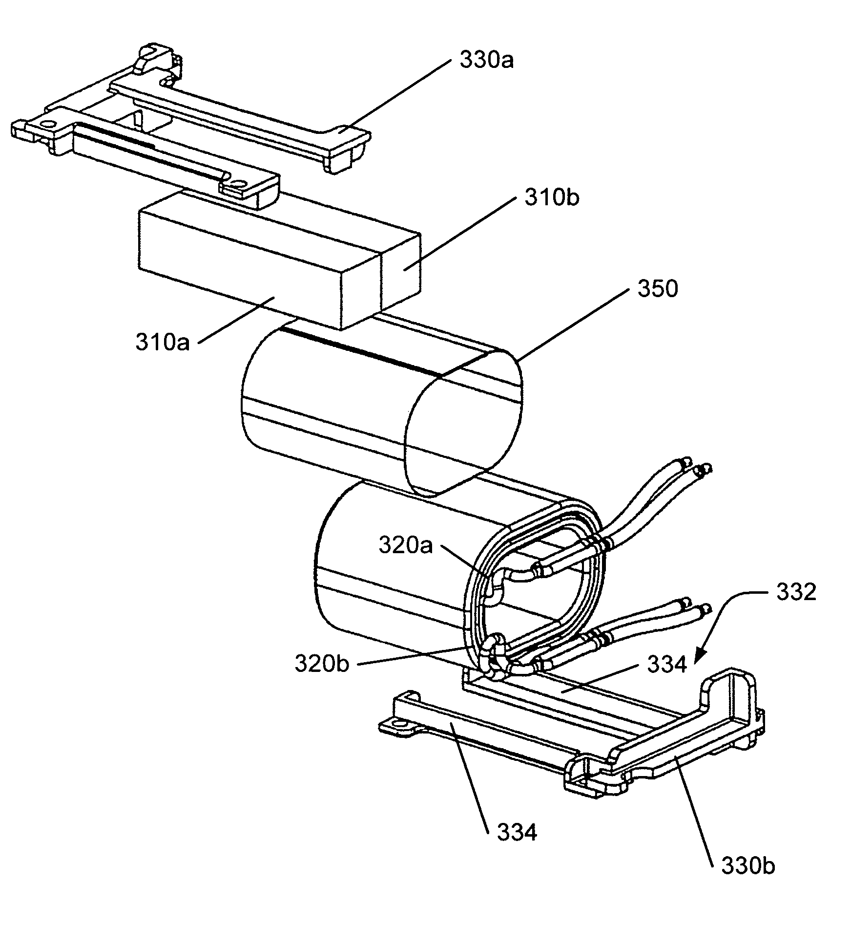
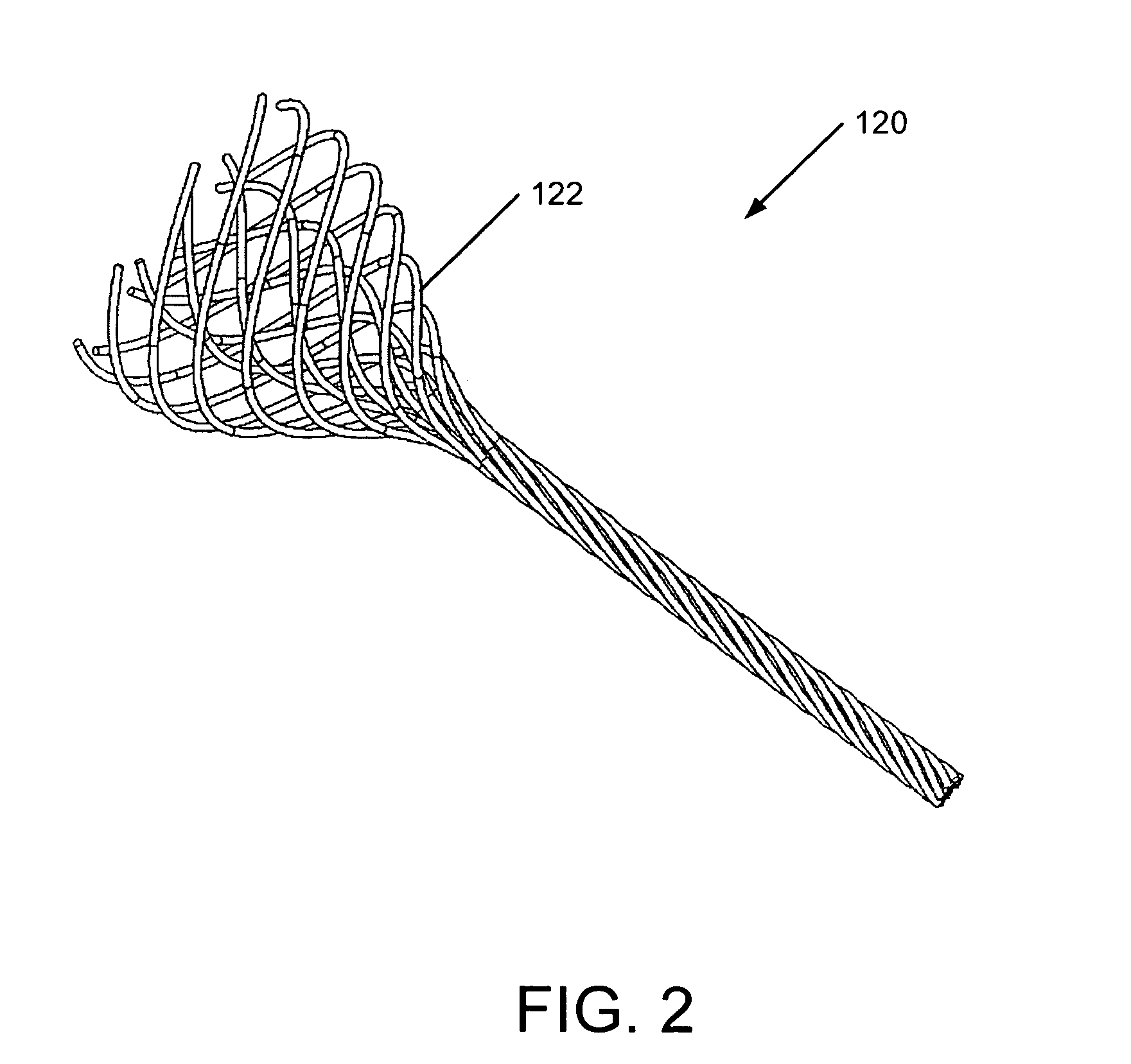
[0016]Specific exemplary embodiments of the invention now will be described with reference to the accompanying drawings. This invention may, however, be embodied in many different forms and should not be construed as limited to the embodiments set forth herein; rather, these embodiments are provided so that this disclosure will be thorough and complete, and will fully convey the scope of the invention to those skilled in the art. In the drawings, like numbers refer to like elements. It will be understood that when an element is referred to as being “connected” or “coupled” to another element, it can be directly connected or coupled to the other element or intervening elements may be present.

[0017]In some embodiments of the invention, an inductor includes a core of magnetic material, such as ferrite or powdered iron. A coil is wound around the core in a solenoid configuration, and separated from the core by a gap that is sufficient to allow coolant, e.g., air, circulation along the l...


PUM

PropertyMeasurementUnit
DC resistanceaaaaaaaaaa
equivalent series resistanceaaaaaaaaaa
magneticaaaaaaaaaa

Abstract

An inductor includes an elongate magnetic core, a coil wrapped around the core and a spacer that separates the coil from the core to provide a coolant passage between the coil and the core. The coolant passage may include an air passage that extends substantially parallel to an axis of the core and that has first and second openings proximate respective first and second ends of the core. The coil may include a twisted bundle of individually insulated conductors. The inductor may be housed in a flux-tolerant compartment, i.e., a conductive aluminum structure that supports eddy currents with relatively acceptable resistive losses.

Description

RELATED APPLICATION[0001]The present application claims priority from U.S. Provisional Application Ser. No. 60 / 482,806, filed Jun. 26, 2003, the disclosure of which is hereby incorporated by reference in its entirety.BACKGROUND OF THE INVENTION[0002]The present invention relates to electromagnetic devices, and more particularly, to inductors.[0003]A high power converter application, such as a PWM-based uninterruptible power supply (UPS), may require low inductance / high current inductors for power conversion circuits, such as rectifiers and inverters. In such an application, it may be desirable to maintain useful inductance to ˜3 times rms rated current. Operational currents may include both a 50 / 60 Hz power component and high frequency ripple currents.[0004]Conventional inductor designs include closed flux path and gapped (discrete & distributed) core designs. Torroidal designs may require a complex winding design, and core heat may be trapped inside such a complex winding. Winding ...

Claims


Application Information

Patent Timeline
Patent Type & Authority Patents(United States)
IPC IPC(8): H01F27/08H01F27/10H01F17/04H01F27/32H01F37/00
CPCH01F27/085H01F27/322H01F17/045H01F27/324H01F37/00
Inventor OUGHTON, JR., GEORGE W.ZENG, LEI WINSTONLYNAM, LARRY VAN
Owner EATON INTELLIGENT POWER LTD
Why Eureka
Try Eureka