Two-way DC-DC converter

A DC converter, bidirectional DC technology, applied in the direction of DC power input conversion to DC power output, high-efficiency power electronic conversion, output power conversion device, etc., can solve the problem that the circuit voltage loss cannot obtain sufficient performance, and large current flows into the switching element , Increased circuit scale and other issues, to achieve the effect of simplifying the structure, shortening the driving period, and suppressing switching loss

Inactive Publication Date: 2005-01-26
HONDA MOTOR CO LTD
View PDF1 Cites 22 Cited by
  • Summary
  • Abstract
  • Description
  • Claims
  • Application Information

AI Technical Summary

Problems solved by technology

[0005] However, in a configuration in which a DC step-up circuit and a DC step-down circuit are installed in parallel between two DC power supply systems, there are problems in that the circuit scale increases, and if they are operated simultaneously, the voltage loss inside the circuit waiting for full performance
[0006] In addition, in the bidirectional DC-DC converter described in the above-mentioned publication, the switching element of the DC-AC conversion part is a switching element for turning on and off a large current. , it has to pass through the unsaturated region of the switching element, so it actually becomes an analog action, so a large switching loss occurs
[0007] Also, in the case of fully synchronously driving the primary-side DC-AC converter and the secondary-side DC-AC converter, when the current of one DC-AC converter flows, if the other DC-AC converter is turned on, a large current flows in Danger of switching elements

Method used


Image

  • Two-way DC-DC converter
  • Two-way DC-DC converter
  • Two-way DC-DC converter

Examples


Embodiment Construction

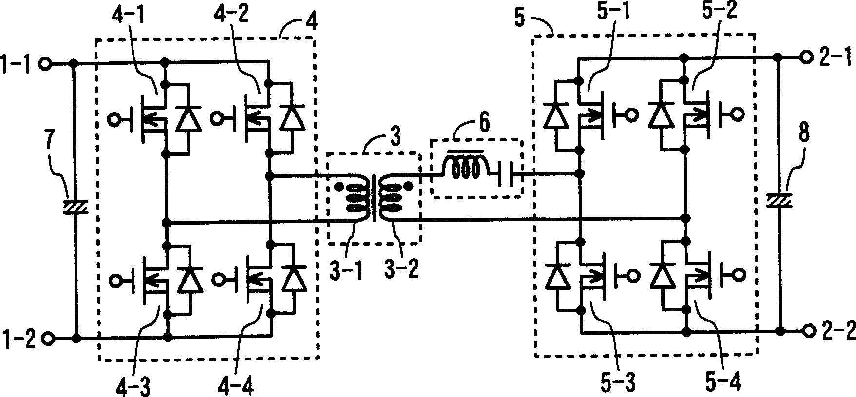
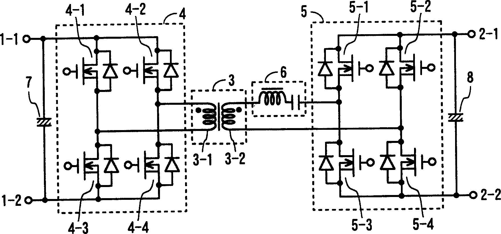
[0020] Hereinafter, the present invention will be described in detail with reference to the drawings. figure 1 It is a circuit diagram showing an embodiment of the bidirectional DC-DC converter of the present invention. In the bidirectional DC-DC converter of this embodiment, the DC power supply connected to the low-voltage side terminals 1-1 and 1-2 and the DC power supply connected to the high-voltage side terminals 2-1 and 2-2 are bidirectionally integrated through the transformer 3. . Hereinafter, the side of the low-voltage side terminals 1-1 and 1-2 may be referred to as the primary side, and the side of the high-voltage side terminals 2-1 and 2-2 may be referred to as the secondary side.

[0021] The transformer 3 includes a low-voltage winding 3-1 on the primary side and a high-voltage winding 3-2 on the secondary side. The step-up ratio of the bidirectional DC-DC converter is determined by the winding ratio of the low-voltage side winding 3-1 and the high-voltage si...


PUM


Abstract

The invention allows DC power supply systems efficiently accommodate each other for electric power, with a simple control system with no fear of a large current flowing a switching element at turning on / off, with less switching loss.A rectification element is connected parallel to each of switching elements 4-1 to 4-4 of a low-voltage side switching part 4, while a rectification element is connected parallel to each of switching elements 5-1 to 5-4 of a high-voltage side switching part 5. By performing switching control either or both of the low-voltage side switching part 4 and the high-voltage side switching part 5 at the same time, an electric power is traded between DC power sources through a transformer 3. An LC resonance circuit 6 is provided between a high-voltage side coil 3-2 of the transformer 3 and the high-voltage side switching part 5, or between a low-voltage side coil 3-1 of the transformer 3 and the low-voltage side switching part 4, so that the current flowing a primary side and secondary side is made to be sine wave, for switching near its zero crossing point.

Description

technical field [0001] The invention relates to a bidirectional direct current-direct current converter, in particular to a bidirectional direct current-direct current converter capable of suppressing switching loss and simplifying a control system. Background technique [0002] Some vehicles and the like are provided with two power supply systems including batteries having different voltage values. When the two DC power systems having different voltage values ​​are connected to each other, generally, a DC step-up circuit and a DC step-down circuit are provided in parallel between the DC power systems, and these circuits are appropriately used. [0003] In addition, it has been proposed to use a bidirectional DC-DC converter in order to obtain a sufficient high-voltage DC voltage with a small-scale circuit when the power is mutually integrated in a DC power supply system. [0004] For example, in JP-A-2002-165448, a bidirectional DC-DC converter is described. The bidirectio...

Claims


Application Information

Patent Timeline
Patent Type & Authority Applications(China)
IPC IPC(8): H02M3/28H02M3/135H02M3/335H02M3/337
CPCY02B70/1475H02M2001/0048Y02B70/1433H02M3/33592H02M3/337Y02B70/1491Y02B70/10H02M1/0048H02M3/33573H02M3/01A45C11/00A45C2011/002
Inventor 江口博之清水元寿
Owner HONDA MOTOR CO LTD
Why Eureka
Try Eureka