3D printing preparation method for injection mold

An injection mold, 3D printing technology, applied in the direction of additive manufacturing, process efficiency improvement, additive processing, etc., can solve the constraints of 3D printing technology application, forming process, forming efficiency and stability can not meet production needs, mold steel cracking and other issues to achieve precise manufacturing, improve forming quality, and reduce cracking

Inactive Publication Date: 2016-05-11
HUAZHONG UNIV OF SCI & TECH
View PDF4 Cites 21 Cited by
  • Summary
  • Abstract
  • Description
  • Claims
  • Application Information

AI Technical Summary

Problems solved by technology

In the 1990s, 3D printing technology has begun to be applied to the rapid manufacture of molds, mainly indirectly manufacturing molds, such as manufacturing molds through silicone soft molds, and indirectly manufactured molds have limitations in performance and service life.
[0005] At present, the use of laser 3D printing technology to directly manufacture injection molds has been studied, but the forming process, forming efficiency and stability still cannot meet the production needs
In particular, metallurgical defects such as mold steel cracking and low melting point alloy element evaporation caused by large thermal stress gradients in the laser forming process have seriously restricted the application of 3D printing technology in the field of injection molds.
[0006] In addition, because 3D printing technology uses laser selective melting and sintering of metal powder, it has special requirements for the fluidity, oxygen content and particle size distribution of metal powder. Therefore, the use of 3D printing technology to directly form injection molds of existing brands is still There are problems in materials and processes, and it is urgent to optimize the composition design, material preparation and process of injection molds

Method used


Image

  • 3D printing preparation method for injection mold

Examples


Embodiment 1

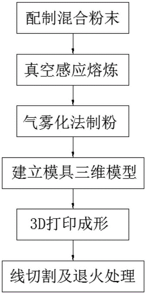
[0028] (1) Configure the mixed powder, and then carry out vacuum induction melting to the mixed powder to form a mold steel billet, wherein the components contained in the mixed powder and the weight percentages of each component are as follows: 0.4% of C element, 0.75% of Si element, Mn element 0.45%, Cr element 14%, V element 0.3%, the balance is Fe element;

[0029] (2) Argon atomization is used to carry out gas atomization powder production on the above-mentioned smelted alloy. The obtained powder is spherical or quasi-spherical, with a particle size distribution of 15-30 μm and an oxygen content of less than 800 ppm to obtain a powder with good fluidity ;

[0030] (3) set up a three-dimensional CAD model of parts on a computer, convert the three-dimensional model into STL format and import it into the selective laser melting rapid prototyping equipment;

[0031] (4) Fill the powder prepared by gas atomization into the selective laser melting rapid prototyping equipment, ...

Embodiment 2

[0034] (1) Configure mixed powder, and then vacuum induction smelt the mixed powder to form a mold steel billet, wherein the components contained in the mixed powder and the weight percentages of each component are as follows: 0.45% of C element, 0.725% of Si element, Mn element 0.4%, Cr element 14.8%, V element 0.25%, the balance is Fe element;

[0035] (2) Use argon gas atomization to carry out gas atomization powder production on the above-mentioned smelted alloy, the obtained powder is spherical or quasi-spherical, the particle size distribution is 30-45 μm, and the oxygen content is lower than 800 ppm, so as to obtain a powder with good fluidity ;

[0036](3) set up a three-dimensional CAD model of parts on a computer, convert the three-dimensional model into STL format and import it into the selective laser melting rapid prototyping equipment;

[0037] (4) Fill the powder prepared by gas atomization into the selective laser melting rapid prototyping equipment, and perfo...

Embodiment 3

[0040] (1) Configure the mixed powder, and then vacuum induction melt the mixed powder to form a mold steel billet, wherein the components contained in the mixed powder and the weight percentages of each component are as follows: 0.5% of C element, 0.70% of Si element, Mn element 0.35%, Cr element 15.6%, V element 0.35%, the balance is Fe element;

[0041] (2) Use argon gas atomization to carry out gas atomization powder production on the above-mentioned smelted alloy, the obtained powder is spherical or quasi-spherical, the particle size distribution is 20-40 μm, and the oxygen content is lower than 800ppm, so as to obtain a powder with good fluidity ;

[0042] (3) set up a three-dimensional CAD model of parts on a computer, convert the three-dimensional model into STL format and import it into the selective laser melting rapid prototyping equipment;

[0043] (4) Fill the powder prepared by gas atomization into the selective laser melting rapid prototyping equipment, and per...


PUM

PropertyMeasurementUnit
particle diameteraaaaaaaaaa

Abstract

The invention discloses a 3D printing preparation method for an injection mold. The 3D printing preparation method comprises the following steps that 1, mixed powder is prepared, and then vacuum induction melting is carried out, wherein the mixed powder is prepared from, by weight percent, 0.4% to 0.5% of C, 0.7% to 0.75% of Si, 0.35% to 0.45% of Mn, 14% to 15.6% of Cr, 0.25% to 0.35% of V and the balance Fe; 2, an atomization powder preparing method is adopted for preparing the powder; 3, a three-dimensional model is established; 4, the injection mold is formed; and 5, the formed injection mold is separated from a substrate, and then the injection mold is placed in a muffle furnace for annealing to improve the plasticity and toughness of the injection mold. According to the 3D printing preparation method, cracking of mold steel in the 3D printing process can be effectively restrained. Meanwhile, C is added to make up ingredient changes caused by element evaporation and carbonization of the injection mold under the action of lasers.

Description

technical field [0001] The invention belongs to the technical field of additive preparation of mold steel, and more specifically relates to a 3D printing preparation method of an injection mold. Background technique [0002] Molds are widely used, and the forming and processing of product components in modern manufacturing industry almost all need to use molds to complete. Therefore, the mold industry is an important part of the national high-tech industry and an important and valuable technical resource. Among them, injection mold is an important process equipment for producing various industrial products. It is a process of replicating plastic products through specific shapes, making mass production of plastic molding products a reality. Therefore, the design level and technical content of injection molds are of great significance to the performance of plastic products. [0003] With the rapid development of the plastics industry and the popularization and application of...

Claims


Application Information

Patent Timeline
Patent Type & Authority Applications(China)
IPC IPC(8): B22F3/105B22F5/00C22C38/24C22C38/02C22C38/04B33Y10/00
CPCC22C38/02C22C38/04C22C38/24B22F5/007B22F2998/10B22F10/00B22F10/38B22F10/364B22F10/28B22F10/64B22F10/36B22F12/41B22F9/082B22F2003/248Y02P10/25
Inventor 魏青松周燕史玉升文世峰滕庆田乐李伟赵晓
Owner HUAZHONG UNIV OF SCI & TECH
Why Eureka
Try Eureka