Surface-treated copper foil low-dielectric substrate and copper-clad laminate and printed wiring board using the same

a technology of low-dielectric substrate and printed wiring board, which is applied in the direction of electrical equipment, metal layered products, domestic applications, etc., can solve the problems of high peel strength, and achieve the effect of excellent low dielectric constant and high peel strength

Inactive Publication Date: 2005-11-29
MITSUI MINING & SMELTING CO LTD
View PDF15 Cites 21 Cited by
  • Summary
  • Abstract
  • Description
  • Claims
  • Application Information

AI Technical Summary

Benefits of technology

[0025]The surface-treated copper foil for a low-dielectric substrate related to the invention is suitable for a low-dielectric substrate which contains any one kind selected from the group consisting of a liquid-crystal polymer, polyfluoroethylene, an isocyanate compound and a low-dielectric polyimide compound. A low-dielectric substrate formed from these materials has an excellent low dielectric constant and it is possible to realize high peel strength by bonding this low-dielectric substrate to the surface-treated copper foil for a low-dielectric substrate related to the invention. This is because as described above, when the surface-treated copper foil for a low-dielectric substrate related to the invention is bonded to these low-dielectric substrates and the copper foil is peeled, a phenomenon which is what is called the cohesive failure occurs within the resin of the substrate.

Problems solved by technology

When the surface-treated copper foil for a low-dielectric substrate related to the invention is peeled from the substrate, a fracture phenomenon occurs within the resin of the substrate and a phenomenon what is called the cohesive failure occurs, resulting in high peel strength.

Method used


Image

  • Surface-treated copper foil low-dielectric substrate and copper-clad laminate and printed wiring board using the same
  • Surface-treated copper foil low-dielectric substrate and copper-clad laminate and printed wiring board using the same
  • Surface-treated copper foil low-dielectric substrate and copper-clad laminate and printed wiring board using the same

Examples


first embodiment

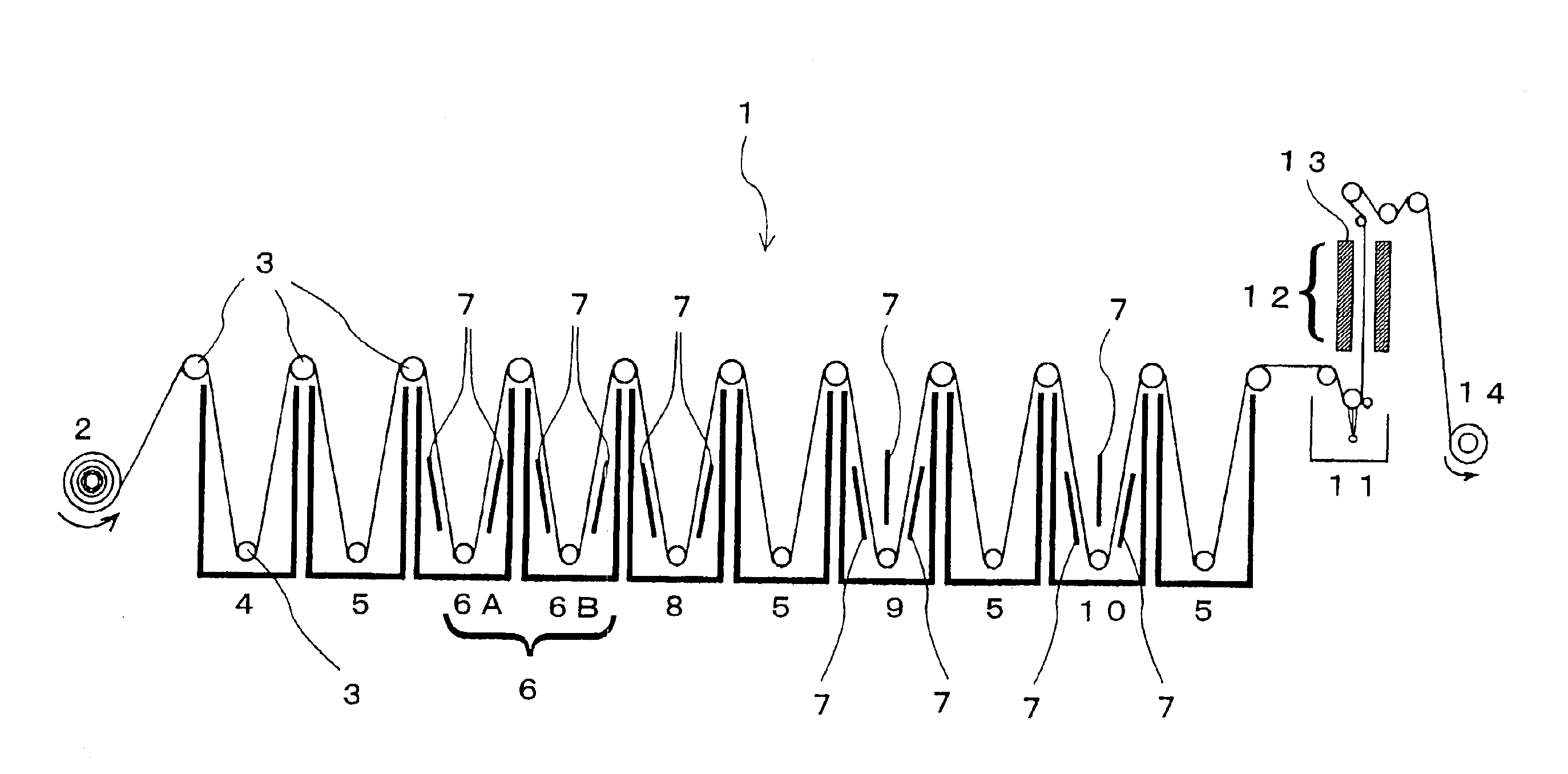
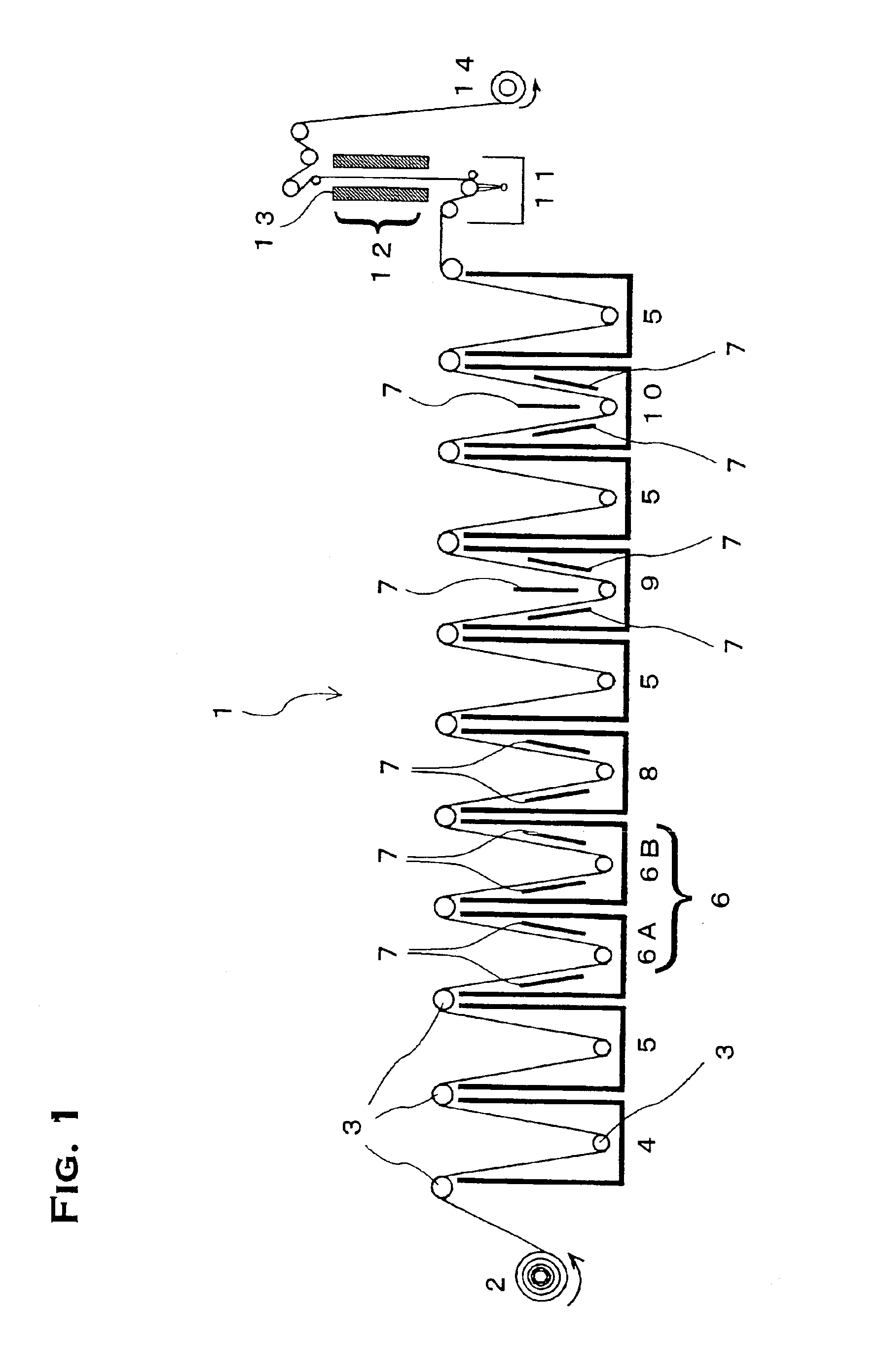
[0030]For the surface-treated copper foil for a low-dielectric substrate of the first embodiment, electrodeposited copper foil produced by being wound in roll form by an electrodeposited copper foil manufacturing apparatus provided with a titanium rotary cathode drum dipped in a copper sulfate electrolysis was used as the raw material. This electrodeposited copper foil wound in roll form was subjected to surface treatment by use of the surface treatment equipment shown in FIG. 1 and the surface-treated copper foil for a low-dielectric substrate of this embodiment, which is suitable for a high-frequency printed wiring board, was produced. FIG. 1 shows a schematic side view of the surface treatment equipment 1. This treatment equipment is of such a type that as viewed from the side, electrodeposited copper foil 2 is guided to each treatment tank by means of guide rolls 3 so as to travel while snaking its way. Each section of the surface treatment will be described below on the basis o...

second embodiment

[0046]In the second embodiment, a description will be given of the result of an investigation into the adhesion of the passivated layer of the bonded surface and a low-dielectric substrate.

[0047]The surface-treated copper foil for a low-dielectric substrate used in the second embodiment was produced by the same method as described in the above-described first embodiment. However, the current density in the nickel-zinc passivation tank 9 in the surface treatment equipment 1 of FIG. 1 was changed in order to control the deposited amounts of nickel and zinc of the passivated layer, (other conditions being the same). As a result, surface-treated foil for a low-dielectric substrate having different deposited amounts of nickel and zinc was obtained. The electrodeposited copper foil used in this embodiment was low-profile copper foil having a nominal thickness of 18 μm (surface roughness Rz: 3.0 μm). Table 2 shows the passivated layer compositions of each surface-treated copper foil produc...


PUM

PropertyMeasurementUnit
particle sizeaaaaaaaaaa
roughnessaaaaaaaaaa
skin depthaaaaaaaaaa

Abstract

The invention provides a surface-treated copper foil which can sufficiently ensure adhesive strength with a low-dielectric substrate used in forming a printed wiring board for high-frequency applications and can minimize transmission losses. There is provided a surface-treated copper foil for a low-dielectric substrate which is used in bonded relationship to a low-dielectric substrate, which is characterized in that a nodular-treated layer constituted by bump-like copper particles is formed on a surface of the copper foil and that ultrafine copper particles are caused to precipitate on the whole surface of the nodular-treated layer and adhere thereto and the roughness value Rz of the surface is 1.0 to 6.5 μm. The surface color of the surface-treated copper foil has L* of not more than 50, a* of not more than 20 and b* of not more than 15. A passivated layer containing at least one kind selected from the group consisting of zinc and nickel is provided on surfaces of the ultrafine copper particles which are caused to precipitate on the whole of the surfaces of the bump-like copper particles of the nodular-treated layer and adhere thereto.

Description

CROSS REFERENCE TO RELATED APPLICATION[0001]This application is a 35 USC § 371 National Phase Entry Application from PCT / JP03 / 07007, filed Jun. 3, 2003, and designating the U.S.TECHNICAL FIELD[0002]The present invention relates to a surface-treated copper foil for a printed wiring board and, more particularly, to a surface-treated copper foil suitable for constituting a printed wiring board using a low-dielectric substrate that is compatible with high-frequency signals.BACKGROUND ART[0003]In recent years, owing to-dramatic progress in information and communication technology, the Internet has changed from a simple medium for retrieving information from media for supplying and receiving various types of information and services. In association with this change, requests for a more comfortable environment, i.e., requirements for “larger quantities of information at higher speeds, in a more real manner” have become strong. In order to realize this comfortable environment (of the Intern...

Claims


Application Information

Patent Timeline
Patent Type & Authority Patents(United States)
IPC IPC(8): C25D5/16C25D7/06H05K1/02H05K3/38
CPCC25D5/16H05K3/384C25D7/0614Y10T428/12014H05K1/0237H05K2201/0355H05K2203/0307H05K2203/0723Y10S428/935Y10T428/12792Y10T428/12063Y10T428/12472Y10T428/12438Y10T428/12722Y10T428/1291Y10T428/12569Y10T428/12903Y10T428/31663C25D5/627C25D5/605H01B3/00
Inventor MATSUDA, MITSUYOSHIKATAOKA, TAKASHI
Owner MITSUI MINING & SMELTING CO LTD
Why Eureka
Try Eureka