Permanent-magnet type electric rotating machine

A technology of rotating electrical machines and permanent magnets, which is applied to synchronous motors with stationary armatures and rotating magnets, magnetic circuit rotating parts, and the manufacture of motor generators, etc. It can solve the problem of large-scale permanent magnet rotating electrical machines and complex assembly And other issues

Active Publication Date: 2012-08-29
KK TOSHIBA
View PDF8 Cites 4 Cited by
  • Summary
  • Abstract
  • Description
  • Claims
  • Application Information

AI Technical Summary

Problems solved by technology

As a result, the size of the permanent magnet rotating electrical machine increases and the assembly becomes complicated.

Method used


Image

  • Permanent-magnet type electric rotating machine
  • Permanent-magnet type electric rotating machine
  • Permanent-magnet type electric rotating machine

Examples


Embodiment Construction

[0023] Various embodiments will be described below with reference to the drawings. In addition, in the embodiments, the same reference numerals are assigned to common structures, and repeated descriptions are omitted. In addition, each figure is a schematic diagram for facilitating understanding of an embodiment, and the shape, size, ratio, etc. differ from an actual device, and design changes can be made as appropriate referring to the following description and prior art.

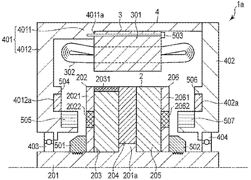
[0024] figure 1 It is an axial longitudinal cross-sectional view of the permanent magnet type rotating electrical machine 1a according to the first embodiment. The permanent magnet type rotating electrical machine 1 a includes a rotor 2 , a stator 3 , and a housing 4 . In the first embodiment, a direction perpendicular to the axial direction is called a radial direction.

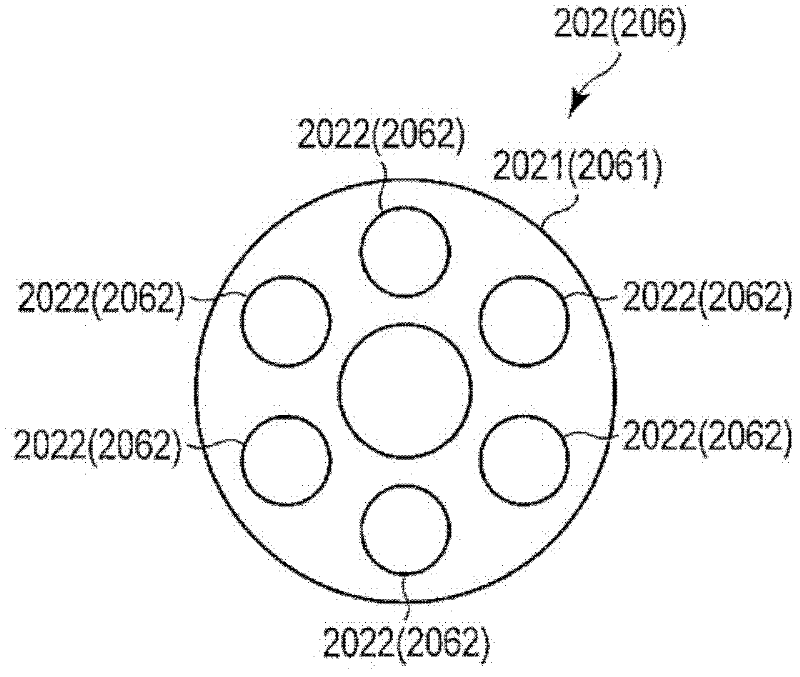
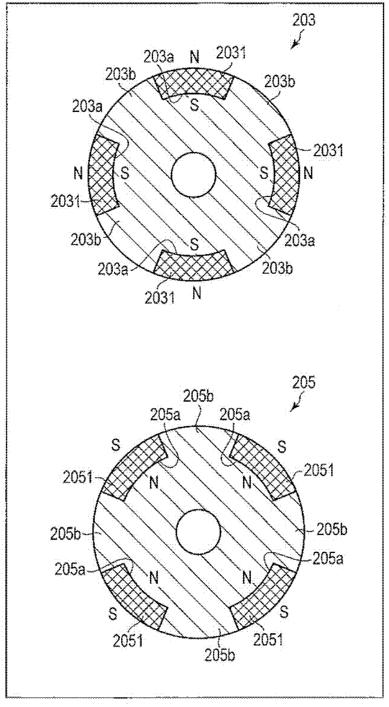
[0025] The rotor 2 includes a rotating shaft 201 , an end plate 202 , a rotor core 203 , a backing plate (Backing Plate) 204 , a rot...


PUM


Abstract

The invention provides a permanent-magnet type electric rotating machine which is not large in size and has good assembly performance. According to one embodiment, a permanent-magnet type electric rotating machine has a stator, a magnetizing coil, a rotor and a case. The stator has an armature coil configured to form a magnetic circuit for driving. The magnetizing coil is configured to form a magnetic circuit for magnetizing. The rotor has a constant magnetized magnet, a rotor core and a variable magnetized magnet. The rotor core holds the constant magnetized magnet. The constant magnetized magnet is arranged closer to the magnetic circuit for driving than the variable magnetized magnet. The variable magnetized magnet is arranged closer to the magnetic circuit for magnetizing than the constant magnetized magnet. The case accepts the rotator and the stator.

Description

technical field [0001] The present invention relates to a permanent magnet type rotating electric machine. Background technique [0002] Carbon dioxide and energy consumption are increasing all over the world, including developed and developing countries. In order to improve this situation, the energy saving of the system is more effective. In electric vehicles, trains, elevators, home appliances, etc., permanent magnet motors are used for high efficiency. For example, in an automobile, a wide operating range is required from a state of low speed and high torque to a state of high speed and low torque. Therefore, the efficiency of the permanent magnet motor decreases in the medium / high speed range or light load. Therefore, variable magnetic force memory motors that directly change the magnetic force of permanent magnets according to operating conditions, and variable magnetic force motors such as field coil type and winding switching type are attracting attention. [000...

Claims


Application Information

Patent Timeline
Patent Type & Authority Applications(China)
IPC IPC(8): H02K21/14H02K1/27H02K1/28H02K1/18H02K15/00H02P6/00
CPCH02K21/04H02K21/14
Inventor 堺和人桥场丰高桥则雄结城和明松下真琴三须大辅新政宪德增正望月资康荒木邦行
Owner KK TOSHIBA
Why Eureka
Try Eureka